INTRODUCTION
The operation of all radiation detectors is dependent upon ionisation of the material from which the detectors are made, whether gas, solid or liquid in nature. Detector operation may be directly dependent on the primary ionisation caused by radiation, e.g. ionisation chambers, or by secondary effects resulting from the primary ionisation, e.g. proportional counters, Geiger counters and scintillation counters. Fundamental principles for detectors operating directly through primary ionisation of gases are discussed in a companion note "Ionisation Chambers", [1], which should be read as the precursor to this note.
At this point, it should be noted that detectors fall into two main categories: a) those which provide a current output and b) those which produce pulse signals. It should also be noted that the second category embraces two sub categories: b1) pulse signals that relate solely to the occurrence of ionising events (particles or photons) and b2) those that additionally convey information relating to the magnitude (kinetic energy) of the detected events.
GAS IONISATION DETECTORS
Gas ionisation detectors of various types are found in all of the categories and sub categories mentioned above with applications restricted by the relatively poor 'stopping power'(energy absorbing capability) of gases in comparison with solid media. Saturated current-generating ionisation chambers for dose-rate measurement (category a) are described in [1].
With the exception of high energy events, their 'primary ionisation' charge-pulse output signals are generally too small for category b) operation, i.e. signals from low energy photon or particle events are lost in the circuit noise of practical amplifying circuits. However high energy alpha particles are readily absorbed in gas and result in charge signals suitable for amplification in low-noise circuits. A special form of saturated ionisation chamber - the gridded chamber - is ideally suited to alpha spectrometry (category b2) operation). The gridded chamber is outside of the scope of this note but a good description of its operation may be found in [2]; needless to say the alpha source must be within the chamber. Incidentally reference [2] is recommended required reading for anyone wanting more detailed information on any of the topics covered in this note.
Figure 2 of [1] illustrates the saturation characteristics of an ionisation chamber. Saturation means that all of the ion pairs generated by the absorption of radiation are collected. Only in exceptional applications are chambers used less than 90% saturated at the highest radiation intensity to be measured.
To examine other types of gas ionisation detector, it is necessary to consider what happens if the applied polarising voltage (and hence electrostatic field strength) is increased beyond values necessary to achieve saturation and the reader is referred to Figure 1., which depicts the effects of increasing field strength beyond the level necessary to collect the primary ionisation and into the region where it imparts sufficient energy to the electrons to produce further ionisation by collision in their progress to the positive electrode.
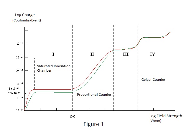
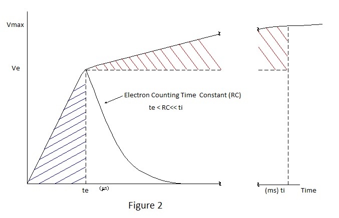
In Figure 1 log. charge is plotted against log. field strength for alpha particles of 5MeV and 10MeV in a gas filled chamber. It can be seen that the magnitude of charge produced, by absorption of particle energy, varies with field strength in a manner which can be separated into four distinct regions; I, II, III, and IV. However it must be stressed that figure1.does not represent a practical situation of increasing polarising voltage applied to a given gas filled chamber. Operation in each of the regions is dependent upon conditions other than field strength alone, and spatial distribution of field strength and gas pressure are important considerations with respect to operation in regions II to IV. E.g.,. the polarising voltage necessary to produce the required field strength for region II to IV operation in a chamber designed for region I operation would be impracticably high and, if applied, would not cause the counter to operate as required, for reasons to be discussed. Nevertheless the figure is valid in the theoretical sense. Region I operation in Figure 1 corresponds to the saturated direct current operation shown in Figure 2 of [1]; the only difference being that the vertical axis of the former expresses charge for individual ionising events and that for the latter, current for a continuous γ radiation flux; categories b2) and a) respectively. Operation in this region is solely the result of primary ionisation i.e. no augmentation or multiplication occurs. Consequently the charge generated is directly proportional to energy absorbed. Figure 2 shows the general nature of category b2) pulse charge collection in respect of the voltage developed across a capacitor. Referring to the figure, it can be seen that the predominant voltage rise occurs in the first few microseconds following an ionising event followed by a smaller voltage rise over a period lasting milliseconds. The initial fast rise is due to the collection of high mobility electrons under the influence of the applied polarising field; the subsequent gradual rise being due to collection of the slow moving ions. It should be noted that the time axis is distorted for ease of presentation but that the shaded voltage-time product areas must be equal. Arrival of electrons and ions at their collecting electrodes is obviously dependent upon where in the inter-electrode space they are formed and rise time periods reflect the spatial distribution of the ionisation, being determined by the longest time of travel and influenced by parameters including dimensions, type of gas, field strength and pressure. |
|
 |
|
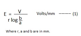
Returning to figure 1 it is can be seen that the charge produced by a given ionising event increases dramatically through the range of field strength bounded by region II but that proportionality with the magnitude of the event is retained. Region II is the operating region for the Proportional Counter and, as its name implies, category b2) pulse operation is achieved in this region. At field strengths in excess of 1000V per mm. in gas at atmospheric pressure, electrons are accelerated to sufficient velocity, and thus kinetic energy, to themselves ionise gas molecules. As discussed in [1], the mean kinetic energy required to ionise gas is typically in the range 25 to 35 eV and increasing the field strength beyond what is known as the Townsend threshold for a gas results in multiplication of the charge due to primary ionisation. The multiplication, which increases rapidly with increasing field, is effectively noiseless and results in greatly improved signal to noise ratio. Its sensitivity to field strength requires that the polarising voltage is very stable. For reasons outside the scope of this note but described in detail in [2] multiplication is limited to about 10,000 in practical counters and such levels are attainable only with careful attention to design and filling gas. With regard to gas, it is usual to fill the counter with a dense inert gas such as argon or xenon with a small amount (about 10%) of polyatomic gas such as methane. The polyatomic gas has the effect of stabilising the multiplication avalanche process, inter alia suppressing spurious pulses due to electrons emitted from the counter walls as the result of soft x-rays produced by ionised or excited atoms of the filling gas returning to the ground state. Returning briefly to the saturated ionisation chamber, particularly one of cylindrical construction, the ratio of the electrode diameters is kept as small as possible to minimise the variation of field strength across the inter-electrode space. In the equivalent proportional counter the converse applies i.e. the central electrode is a very thin wire. The field strength at radius 'r' between coaxial cylinders radius 'a' (smaller) and radius 'b' (larger) with Voltage 'V' between them, is given by the expression :- |
|
 |
|
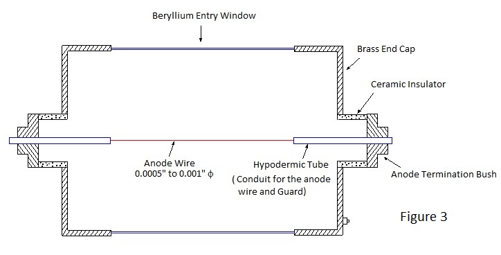
From this it is apparent the closer r is to a and the smaller the ratio of b to a, the greater is the field strength and consequently conditions for gas multiplication can occur very close to a thin wire with moderate applied voltage. Remarkably this is exactly what is required in a proportional counter; as electrons due to primary ionisation occurring within the multiplying volume surrounding the wire may not be fully multiplied before the charge is collected at the wire. Therefore, for good amplitude resolution, the multiplying volume must be small. Electrons produced outside of the multiplying volume drift towards the wire under the influence of increasing field strength and generally receive maximum multiplication. Typically the wire radius 'a' is 10μm and the multiplying region extends to a radius 'r' of a few tens of μm only. A section through a typical cylindrical counter is shown in Figure 3. The tubular sleeves at each end of the anode wire serve to define the collecting and multiplying volumes, reducing spurious effects due to the wire termination. Counters may be sealed as shown in the figure or gas flow, with the counting gas continuously refreshed, according to application. Also according to application, they can be made spherical for 4π counting or in a multi-wire pancake form. Because of the noiseless amplification, proportional counters can be used for low energy ionising events and are particularly suited to x-ray spectrometry. Poor stopping power precludes the practical use of proportional counters for category b2) photon counting much beyond 100keV. Although the gas amplification is noiseless its limiting value is such that additional electronic amplification is required to produce voltage signals suitable for processing and for x-ray spectrometry low noise circuits are essential for good resolution. With good amplifier design resolution is primarily dependent upon the statistical variance in the number of primary ion pairs produced by a given ionising event. Because of the 30 plus eV mean ionisation potential for gases, primary ion pairs are relatively few in number at low energies, e.g. absorption of a 20keV photon results in about 500 ion pairs with a 2 σ spread of about 90 ion pairs; equivalent to full width half maximum (fwhm.) resolution of about 20%.
|
|
 |
|
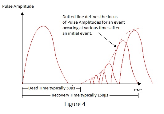
Nothing has been said about the action of positive ions in the proportional counter. Positive ions play little or no part in its operation. Their mobility in a field strength which diminishes in the direction of collection precludes them from gaining sufficient kinetic energy for them to cause ionisation by collision. With moderate electron multiplication and an appropriate differentiating time constant, their effect on proportionality is insignificant. However for each multiplication an ion is formed and the ion population in the counter is much increased by a high multiplication rate, particularly at high count-rates. The slow moving ions constitute a space charge which ultimately distorts the field around the anode wire. Their effect, therefore, is to set a maximum limit to the gas multiplication ratio which can be achieved and, if the polarising potential is increased beyond the limiting value, energy proportionality is lost. This is the beginning of region III of Figure 1 where the 5MeV and 10MeV curves begin to converge. At the upper limit of this region convergence is complete and the charge pulses due to ionising events have fixed magnitude irrespective of energy i.e. the counter is useful only for category b1) counting. The magnitude of the charge (multiplication) continues to increase with applied voltage as shown by the sharply rising characteristic between Regions III and IV. Region III operation does not find wide application although it does have counting rate advantage over the next counter operating mode; region IV. From expression (1) it can be deduced that, for a given voltage applied to a coaxial structure, the radius for which the field strength is sufficient to cause multiplication can be extended by reducing the ratio of radius 'b' to radius 'a' and consequently electrode 'a' can be a wire thick enough to be self supporting if 'b' is reduced. This is the typical configuration for a counter designed to operate in region IV. In region IV the charge produced increases much less rapidly with increasing field strength but the charge produced is massive. In fact, without sufficient limiting resistance, the counter can go into continuous glow discharge. Region IV is known as the Geiger region and the charge vs. field strength characteristic is known as the Geiger 'plateau'. Any ionising event in the Geiger counter can result in a fixed charge pulse irrespective of the original energy and the pulse can be large enough to be applied to counting circuits without amplification. A discrete packet of charge is formed and continuous discharge prevented by the action of positive ions in conjunction with the limiting resistor. As the charge multiplies following an ionising event their population density around the anode wire becomes sufficient to reduce the field - already diminished by volt-drop across the limiting resistor - such that conditions for multiplication no longer exist. Because of the low mobility of these blanketing ions the discharge becomes non-sustaining and terminates; a processes known as quenching. If the counter is filled with a pure gas such as argon or neon the quenching action is unreliable but the addition of a small amount of poly-atomic gas or vapour makes it definite. A few per cent of alcohol was often used in a filling gas mix at about one third of atmospheric pressure (Geiger counters are always sealed) until this was generally superseded by the use of halogen quenching agents in commercially available counters. The quenching action lasts until most of the positive ion charge has been collected and the reader might ask "What happens if another ionising event occurs during the quenching action?" The answer to this is that for a period of time nothing at all happens. This period, known as the dead time, lasts typically a few tens of micro seconds to a few hundreds of micro seconds depending upon the design and size of counter. Full charge-pulse magnitude is not attained immediately following a dead period and a second ionising event falling shortly after it produces a charge pulse of reduced magnitude. The magnitude of charge pulse progressively increases with the period of time that the second ionising event occurs after a dead period; the time period to full recovery being known as the recovery period. A typical pulse charge vs. time profile for consecutive ionising events is shown in Figure 4. Because recovery is determined by the mobility of positive ions, Geiger counters operate at moderate count-rates and dead time correction must be applied to indicated count-rates of more than a few kHz. if serious under reading is to be avoided. To remove the uncertainty due to the possible miscounting of events falling within the recovery period, some instruments embody the facility of removing the polarising voltage after each detected event for a period equal to the full recovery time. This is known as electronic quenching.
|
|
 |
|
Geiger counters are made in volumes ranging from a fraction of a cubic centimetre up to several hundred cubic centimetres. 'b' to 'a' ratios are arranged to require a polarising voltage of typically 600V for halogen quenched counters. In common with other devices operating at relatively high levels of gas ionisation, operating life is limited by a phenomenon known as gas clean-up. Halogen quenched counters are better in this respect than alcohol quenched ones. With suitable construction, Geiger counters can count gamma photons alone, gamma photons and beta particles and gamma photons, beta particles and alpha particles. They can be arranged to respond to particles alone but the technique is outside of the scope of this note. In addition to category b1) pulse counting, Geiger counters can be used in the category a) current mode to indicate radiation flux analogous to dose-rate. Due to the effect of dead time, the relationship between current and flux is approximately logarithmic and is usable over a wide range. Because the Geiger tube produces sufficient current to drive a moving coil meter the principle can be used to produce an extremely simple dose rate meter. To achieve the required energy response to indicate absorbed dose-rate, it is necessary for the Geiger counter to be surrounded by a special graded multilayer absorber such that the proportion of photons entering its sensitive volume varies with energy. |
|
SOLID STATE DETECTORS A simple generalisation of the foregoing is that gases are good insulators and the effect of ionisation is to make them conductive. Gases, however, have poor 'stopping power' and consequently category b2) gas counters for energetic photons become impractically large. How much better would be the situation if ionisation could be produced and collected from a dense solid insulator? Insulators are impractical because, other than breakdown, there is no effective charge transfer mechanism for locally produced ionisation. However semiconductor materials satisfy this condition and provide the basis for the design of what are effectively solid- state saturated ionisation chambers. Semiconductor detectors can be designed to provide category a) current signals as well as category b) charge-pulse signals similar to their gas ionisation counterparts. In addition to greater stopping power, semiconductor detectors have other advantages relative to gas detectors but, in the usual way of things, they also have disadvantages; as will be discussed in due course. Semiconductors are generally of four covalent-bond single crystal structures, either single materials from group IV of the periodic table such as carbon, silicon and germanium or 'fabricated' group III-V or group II-VI compounds such as gallium arsenide and cadmium telluride respectively. Although many of these materials are dense and thus have high stopping power, it is currently not possible to grow crystals of some of them large enough or pure enough for general application to the measurement of all types of radiation. Their use, therefore, is directed to the specific applications for which their peculiar properties are best suited. To ionise a semiconductor it is necessary for atoms to receive energy from incident photons sufficient to release electrons from the valence band and to raise them to the conduction band, i.e. to 'jump the band gap'. The band gaps for silicon and germanium are about 1.11V and 0.66V respectively at room temperature and those for the fabricated materials somewhat higher. They increase with reducing temperature. As with gas detectors, the mean energy to create an electron-ion (hole) pair (W) is greater than the theoretical ionisation potential; that for silicon being about 3.5eV. This means that, for a given energy absorbed in a silicon detector, approximately 10 times more primary ion pairs are generated than for the same energy absorbed in a gas detector. As discussed in connection with gas proportional counters, statistical variation in number of primary ion pairs governs the achievable resolution and thus semiconductor detectors have a distinct advantage in this respect. However the output charge is very small and there is normally no facility for noiseless amplification, as produced by the proportional counter, so noise in the essential following amplification becomes a crucial factor in the determination of resolution. Here the semiconductor detector is at disadvantage; the low ionisation potential means that ion pairs are generated thermally at room temperature constituting a leakage current. This current flows in the input circuit of a following amplifier and acts as a source of noise [3]. To minimise the effect of input current noise it is essential to cool both detector and amplifier with liquid nitrogen to approach the theoretically attainable resolution. Leakage current is also highly dependent upon the presence of impurities in the semiconductor material and consequently only highly refined, and hence expensive, material can be used for the fabrication of detectors in ultra clean conditions. Another aspect of performance where the semiconductor detector has an advantage over its gas filled counterpart is speed. Electron-hole mobility in semiconductors is much greater than electron-ion mobility in gases so the pulse charge forms more rapidly in the former. Semiconductor detectors can therefore potentially operate at higher count-rates but noise is also a limiting factor with regard to this aspect of performance [3]. How are semiconductor detectors made? It has been mentioned the archetypical solid detector has a region of intrinsic (pure) semi-conducting material between polarising and collecting electrodes and that the material must be dense and of adequate depth or volume to fully absorb incident radiation for category b2) spectrometric counting. It has also been mentioned that the material needs to have sufficient band gap if resolution and efficiency are not to be impaired by ambient temperature. Currently no universal material which fulfils all of the requirements is available. For category b2) counting of x and γ gamma radiation the material used is 'hyper pure' germanium, as this is dense and can be produced with sufficient depth/volume. Hyper pure means that the material contains virtually no acceptor or donor impurities to produce what are known as majority carriers. Unfortunately germanium has a low band gap and is unusable at room temperature due to thermally generated minority carriers and consequently it needs to be cooled to 77K (boiling nitrogen temperature) to operate satisfactorily. With depth suitable for γ counting the required polarising voltage is similar to that required for gas proportional counters i.e. 1 to 2.5kV. Dense compound semiconductors such as Mercuric Iodide and Cadmium Telluride have sufficient band gap to give good resolution at room temperature but currently it is not practicable to produce crystals large enough or pure enough for other than restricted application and germanium reigns supreme for high resolution spectrometry. For less penetrating β and particularly α radiation the relatively low density of silicon is not a handicap and its higher band gap relative to germanium permits room temperature operation. Also because of the much reduced depth required to fully absorb the particle energies, the 'carrier free depth' can be the depletion region produced by reverse biased pn. junction. Particle detectors must be constructed such that the depleted region lies just beneath the surface upon which the particles are incident, particularly for alpha particle detection. The particles must pass through dead and active silicon layers to enter the sensitive region and through an additional aluminised layer for operation in ambient light conditions. For alpha particles especially, these layers must extremely thin if significant energy is not to be lost from particles traversing them. With suitably pure silicon (much purer than that used for transistors and integrated circuits) detectors can be made with surface barrier junctions (Shottky diodes), diffused junctions and latterly ion implanted junctions. Detectors of these three types have been used for alpha monitoring in environmental air samplers. To minimise response to unwanted 'background' radiation it is usual to employ a depletion depth sufficient only to absorb the most energetic particles to be measured. A depletion depth of about 70 μm is suitable for alpha particles of energy up to 10MeV and a depth of about 4 to 5 times this for energetic beta particles. Depletion depth is proportional to the square root of the product of polarising (reverse bias) voltage and resistivity of the silicon and for 3000W-cm base material the polarising potential ranges between approximately 10V and 200V according to application. Junction detectors tend to be of relatively high capacitance and amplifier noise needs to be minimised, particularly with large area units, if good resolution is to be achieved [3]. Capacitance varies inversely with the square root of the polarising voltage, the magnitude of which may therefore be optimised to suit an application. As mentioned at the beginning of this section, semiconductor detectors may be employed for category a) current output applications forming a basis for compact dose-rate monitors.
LIQUID SCINTILLATION DETECTORS The scintillation phenomenon can also occur in certain liquids and the light produced in a liquid cell can be coupled to a photomultiplier tube in a similar manner to that from a solid counter. Liquid scintillation counting is laboratory technique outside of the general scope of this note. It is used for category b1) counting for applications where it is necessary for the radio-active material to be mixed with the scintillant. Air sampling for tritium is a major use of liquid scintillation counting. In this application case air is bubbled through scintillant such that hydrogen (and hence tritium) is deposited in the scintillant in the form of water, by catalytic combination with oxygen. The process is quite complex but it provides an extremely accurate method for tritium assay.
References: [1] Ionisation Chambers - See Page 4 of this website - a companion to this note. All content is free to use. |
