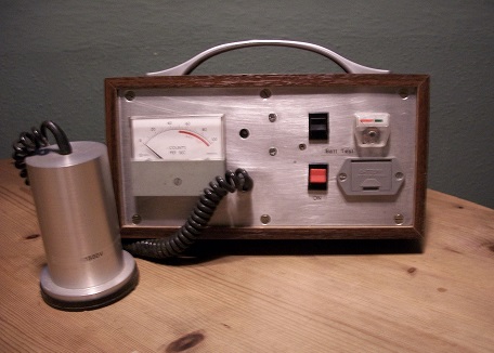
Shown below is my home brewed Geiger Counter (Everybody should have one!)
Construction of the instrument was commenced about ten years ago, intended to be a simple project to interest my grandson. As is the case with many of my efforts, it never progressed beyond the circuit breadboard stage and the breadboard gathered dust until a couple of months ago when I decided to put it in a case. Originally it was intended that the detector was to be a small halogen quenched Geiger tube but a serendipitous find at a boot sale resulted in the use of the large alcohol quenched tube shown in the picture. The vendor clearly didn’t understand what he was selling because item was offered as ‘some sort of microphone’ and, recognising it for what it was, I purchased it for 50 pence - an incredible bargain.
How the vendor came by it is best left unquestioned.
. The reader might ask how might a domestic user have access to anything with which to demonstrate the operation of a Geiger counter? The Americium 241 source in a domestic smoke alarm is an enthusiastic emitter of α particles, 60keV γ photons and 18keV x-rays although the source will need to be removed from the alarm to monitor the copious α emissions. YOU ARE NOT TO DO IT!! Soaking a piece of blotting paper with high potash content liquid fertiliser and allowing it to dry will furnish a source of energetic Potassium 40 γ photons and powdering a brazil nut might be interesting. Before anyone gets alarmed, it must be said that Geiger counters are very sensitive and that the levels of radiation detected are not harmful. The counter depicted clicks away two or three times a second due to the natural background radiation produced by Uranium in the ground and building materials *.
*See Pages 5 & 6 of this website.
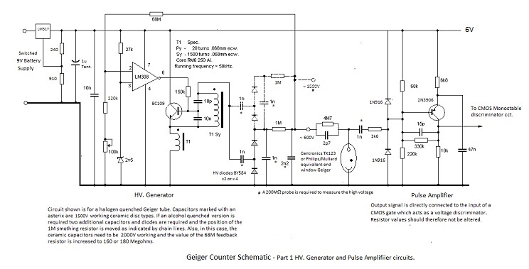
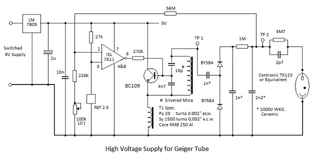
The first half of the schematic covers the 'high' voltage Geiger tube supply generation, the Geiger tube circuit and the following amplifiier. The high voltage generator employs a sine wave oscillator of the type described in Page 8 of this website. This accounts for a major proportion of the power consumption which is low enough for an MN1604 9V alkaline battery to be used as the primary power source.
Two versions of the high voltage supply are covered by the schematic: a nominal 600V supply for a halogen quenched counter is shown with the additional components for the 1500V supply for an alcohol quenched counter shown as chain lines. Different values of feedback resistance are necessary to determine and stabilise outputs. The 600V version operates from a stablised 5V supply and the higher voltage version from a 6V supply, either of which are produced by an LM317 integrated regulator circuit with appropriate component values.
Pulses from the anode terminal of the counter are capacitively coupled to a single transistor amplifier circuit. This amplifier has direct coupled feedback to determine the quiescent voltage at its output terminal. This is important because the output is directly connected to the input of a CMOS gate which acts as a discriminator against spurious noise pulses as is shown in the second half of the schematic below:-
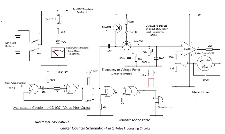
The second half of the schematic shows the CMOS disciminator circuit mentioned above. This is a monostable multivibrator circuit designed to produce a 50μs wide positive going rectangular output pulse each time a signal from the Geiger tube amplifier exceeds the switching theshold of the input CMOS gate. The output of the monostable circuit is routed to two further circuits. One of which is a similar monostable circuit which produces a 5ms wide pulses to drive a Piezo electric buzzer; producing characteristic Geiger Counter clicks. The other circuit is a ratemeter ( frequency to dc. converter) which produces a direct voltage output to drive a moving coil meter which indicates the detected countrate. The ratemeter circuit is effectively a diode pump which uses transistors in lieu of diodes to produce a voltage output which is a linear function of the incoming pulse frequency. It is designed to produce an output of 2V for an input of 100 counts per second. The output of the ratemeter circuit is fed to a voltage to current conversion circuit which employs an LM308 operational amplifier to drive a 500μA fsd. meter movement which is scaled 0 to 100cps.
An Application
The Geiger counter may be used to check the activity of the Americium source from the smoke detector
provided the latter can be removed without damaging it. The activity of the Americium 241 souce is a measure of the number of alpha particles emitted per second in all directions and the source is small enough for this emission to considered to be isentropic or 4π.
37% of the α particles emitted are accompanied by a 60keV γ ray and if these can be counted in absence of the αs, with known geometric efficiency, the α activity of the source can be calculated. The α particles are absorbed by about a cm of air so, if the detector is placed more than a cm from the source, only the γs will be counted. If the detector is placed closer, a piece of baking foil across the detector entry window will eliminate the αs. and low energy x-rays which are present. The low γ energy of 60 keV is pretty much ideal because the proportion of photons back scattered from material behind the source is small at this energy. However back-scatter can be minimised and, consequently accuracy can be improved, by placing the source on a layer of lead roof flashing.
It is of course necessary to do a background count before making a measurement with the source.
This background count must be subtracted from a source count of equal duration and for accurate results an add-on digital scaler-timer is required. However one can get surprisingly close to the true figure by observing the analogue meter indications.
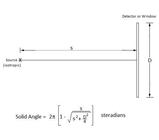
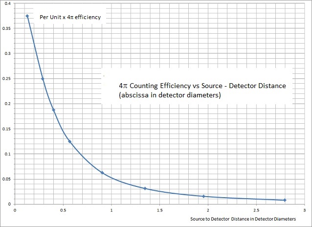
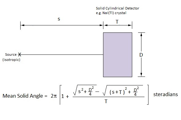
Geometric efficiency is the proportion of the total 4π emanation which impinges on the Geiger tube entry window.
This is dependent upon source to detector distance and the diameter of the entry window and it may be calculated as shown in the figures below. In the figures distance is expressed in terms of detector diameters, in order to provide a general expression and also in graphical form to permit interpolation of distances measured conventionally.
The monitor described in the foregoing was a ‘fait accompli’ long before the webpage was constructed and as such circuit description and measurement details are not as comprehensive as those for other projects described in this site..
To rectify this omission, the author has decided to breadboard a version which employs a halogen quenched Geiger-Muller tube.
This is intended to be a progressive exercise enabling waveforms and voltages to be recorded as the project develops.
Again the circuit will be constructed using stripboard which is the only option available to the author who is aware that, sadly,‘t.t.b.’ components are becoming increasingly difficult to source.
A prospective constructor might have a facility for constructing a more modern version employing surface mount components. A protype surface mount version of the ‘high’ voltage generator circuit has been constructed.
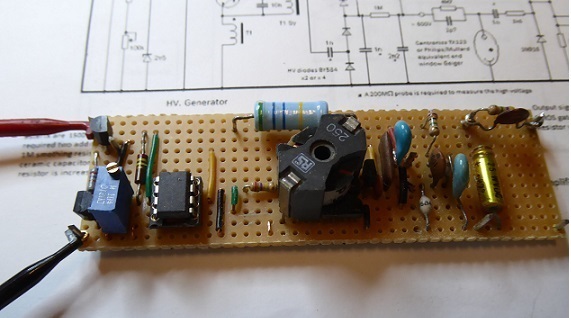
The layout shown above is far from optimal, even for stripboard, and tracks are cut or spotfaced as necessary. It does however give an indication of the space required for the components. Without the amplifier-discriminator circuit it draws 7mA which is well within the capability of an MN1604 9V alkaine battery.
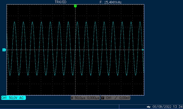
As can be seen from the oscilloscope trace shown below,the waveform at TP1, is a clean sinewave of approximately 600V pk. to pk. amplitude.
Note that the indicated frequency of approximately 25kHz is half of of that expected for the oscillator transformer shown in the schematic. The reason for this is that, to avoid the hassle of winding a new transformer, an existing example has been used. For this example, primary and secondary windings are actually 30 and 2200 turns respectively and the inductances are correspondingly greater. They are wound on an RM8 size AL250 core. The 20/1500 turns winding ratio, specified in the schematic, can be wound more conveniently on a smaller RM7 AL250 core, doubling the runnng frequency.
Additionally the vertical axis of the oscilloscope display is uncalibrated; it being necessary to attenuate the signal in accordance with the display amplitude limit for the oscilloscope.
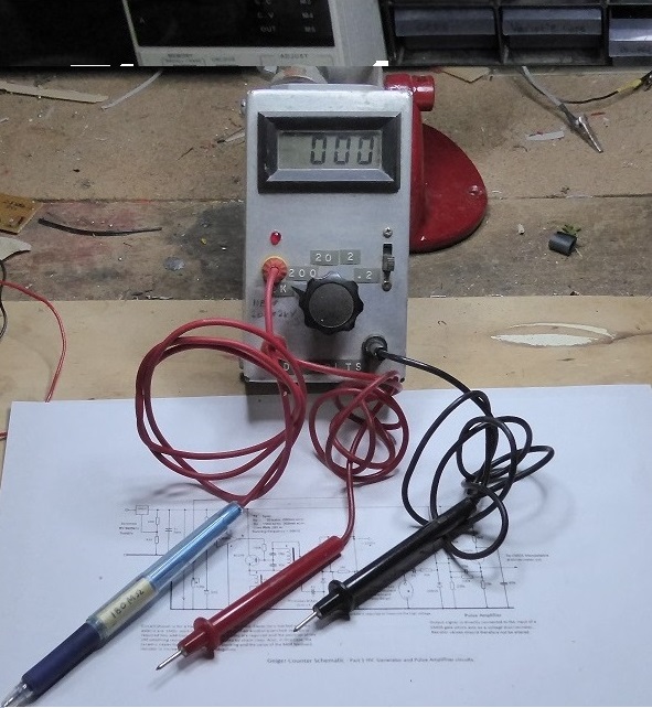
The range of output voltage afforded by adjustment of the potentiometer facilitates plotting of the operating plateau for the Geiger-Muller tube if desired for optimal setting. Measurements of the voltage at TP2 were made using a 180MOhm probe comprising ten series connected 18MOhm resistors housed in the shell of a 'BiC' pen as is also shown in the following figure. The probe is used in conjunction with a home brewed a 'DMM' which is arranged to have a 20MOhm input resistance on a 200V range. It is connected to a separate input socket facilitating measurement of other DC voltages via a direct probe without its removal.
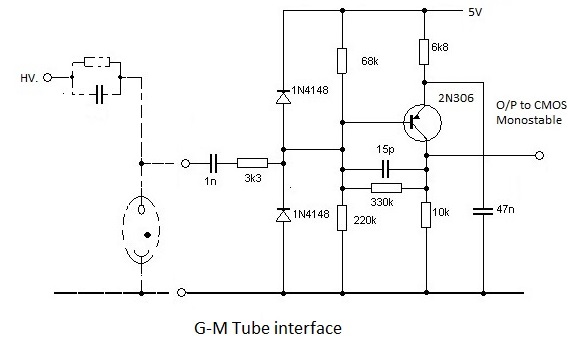
An 'amplifier'/pulse conditioner interface circuit is required to render the Geiger-Muller tube output pulses sutable for digital processing by CMOS logic circuits. This interface, in combination with a CMOS monostable circuit, produces fixed duration (50μs) logic pulses for further processing. In addition it discriminates against spurious low amplitude (noise) pulses and imposes a fixed inter-event dead time of 50μs. The schematic for the direct coupled interface circuit is shown below. It is arranged such that the quiescent output voltage is less than the maximum '0 state' input level for CMOS operating from a 5V supply and consequently it acts as a pulse amplitude discriminator.
The pulse at the anode of a Centronics TX123 halogen quenched tube, operating with its specified anode voltage of 530V and responding to the 60keV gamma ray emissions from a smoke detector source, is shown below.
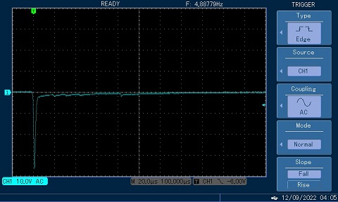
From this it can be seen that a typical anode pulse has an amplitude of around 35V and a baseline duration of approximately 10μs with the 4M7Ω load.
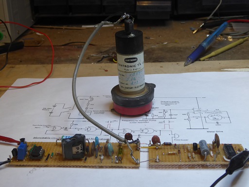
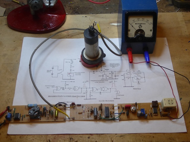
The additional pulse processing breadboard assembly is pictured in the following photograph, together with the TX123 Geiger Muller tube under test. It should be noted that the TX123 entry window is protected by an ad. hoc. rubber cap assembly. This cap incorporates an aluminium disc which absorbs the alpha particle emissions (and probably the 18keV x-rays) from the Am 241 smoke detector source. Circuit development work with the fragile alpha particle entry window unprotected is not recoomended!
The red pedestal on which the geiger tube is mounted comprises the source/ion chamber assembly from an early smoke detector and which, conveniently, is of the ideal diameter for stable support of the TX123 tube. (More recent smoke detectors employ an assembly of smaller diameter).
The additional interface ciruitry required to discriminate against spurious pulses and to provide pulses suitable for driving a linear ratemeter circuit and a 'click' sounder are shown in the schematic which follows:-
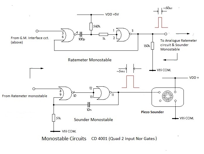
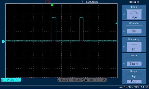
Normally there would be lttle point in displaying a scope trace of the output at pin 3 of the CD4001 integrated circuit but a trace is shown below to illustrate a characteristic of random events such as radioactive decay. From the trace it can be seen that the frequency counter registers a rate of just over 5 cps. Corresponding a following event would be expected just less than 200ms later on average. However the trace shows a following pulse after an interval of 300μs.
Random events are like buses - you wait a long time for one to come along and several arrive in close succession!
An analogue ratemeter circuit will of course be dependent upon availability of a suitable moving coil meter movement. I was fortunate in having a 500μA movement -already scaled in counts per second- to hand when I my constructed my original counter and full information with regard to its application is provided in the second part of the schematic at the top of this page.
Frequency is converted to voltage by a 'linearised' diode pump circuit which employs transistor in lieu of diodes to avoid non linearity attendant upon the use of simple diodes. The low emitter input impedances of the transistors permit operation with input pulses of 'short' duration and the high collector impedances render the circuit operation independent of the d.c. output voltage.
The pump output voltage is given by Vout = nCR Ein - where n = frequency, C is the input capacitor value, R is the resistance between the base of the PNP transistor and common rail and Ein is the rail voltage (5V in this case). A MD7021 PNP/NPN dual transistor package has been used in the pump circuit purely for convenience. Single transistors, e.g. 2N3906 and 2N3904 respectively, are equally suited.
The pump output voltage is applied to a voltage to current converter circuit which employs an operational amplifier to combine high input impedance with a 'constant' current output to drive the meter movement.
As for a Piezo sounder to convert the 5ms duration output pulse from the sounder monostable into characteristic Geiger clicks; many of the available circuit board mounted sounders operate with a five volt supply with a cmos control signal.
Except for an emitter follower buffer circuit to permit the 50μs duration output from the ratemeter monostable to be connected to an external scaler-timer device, all of the components for a 'halogen quenched' version of the Geiger counter circuit are mounted on three stripboard sub assemblies as shown
below.
Apart from the input capacitor for the analogue ratemeter circuit (red component on the left of the right-hand stripboard assembly) none of the components need to be close tolerance items and that needs only be within +/- 5% of the specified 10nF value.
However the working voltage of the 1nF capacitor which couples the Geiger tube anode to the input of the interface circuit must be 600V or more.
Because the ratemeter indication is effectively independent of input pulse duration, calibration can be effected using a 100Hz. square wave from a signal generator provided that the peak to peak amplitude equals VDD, i.e. 5V.
With this signal applied via the input capacitor, calibration is effected by adjusting the 50kΩ multi-turn potentiometer (blue) for full scale deflection of the moving coil meter.
The cmos controlled piezo buzzer shown was originally sourced from RS Components but it is no longer listed. However an alternative should not be difficult to find. It is specified for 6V operation, as used for the alcohol quenched counter, but it works well with the five-volt signal and supply for the halogen quenched version; producing a satisfying click for the 5ms duration pulse from the sounder monostable