Back to Homepage & Index

This Page - Ionisation Chambers

INTRODUCTION

Although a number of methods for the measurement of energy deposition due to penetrating ionising radiation have been developed, the fundamental instrument remains the gas ionisation chamber.  In fact the original unit for radiation exposure dose, the Röentgen, was defined in terms of the primary ionisation produced in one cubic centimetre of dry air at standard temperature and pressure; primary ionisation being that produced directly by the incident radiation i.e. not subject to the gas amplification which is employed in ion chamber derivatives, proportional counters and Geiger counters.
Ionisation results from the absorption of energy from incident x ray or gamma photons in any medium and is directly measurable in gases or semiconductors.  Current dose/dose-rate units require calibration in terms of energy absorbed in given mass of medium (usually tissue) but the practical method of measurement - in this case ionisation produced in gas within a chamber - remains the same.
The relationship between the practical measurement of exposure dose/dose-rate and the absorbed dose/dose-rate is discussed at the end of this note.


As with many fundamental units, the unit for exposure is defined in a manner which is impractical for everyday use; calling for measurement in free air with no surrounding material to absorb or scatter the incident radiation.  Such a free air chamber may be designed for use in a Standards Laboratory but for practical measurement it is necessary to contain the air in a closed chamber which houses the collecting electrodes and in many cases constitutes one of them.

This note attempts to examine in a non-mathematical manner, the advantages and disadvantages of enclosing the gas within the confines of a sealed chamber.  Before dealing with the practical ionisation chamber, it is perhaps worthwhile to consider the phenomenon of gas ionisation and how it is caused.


FUNDAMENTALS OF IONISATION

X or g gamma radiation passing through the volume of gas in a chamber loses some of its energy by ionising the gas within.

This means that for some of the gas atoms an electron orbiting the nucleus is ejected; leaving each of these atoms with a positive charge equal to the negative charge of the electron ejected - removal of a negative charge from a neutral body composed of equal numbers of positive and negative charges leaves the body with a net positive charge.  These positively charged atoms are called ions and thus the effect of the radiation is to produce pairs of electrons and ions within the gas, normally referred to as ion pairs.

Unlike charges attract so the reader might ask, ‘why don't the pairs recombine immediately’?  The reason is that the electrons are emitted with sufficient velocity to remove them from the range of influence of the parent atom, somewhat akin to the concept of escape velocity for space probes.  In fact preferential recombination, as this called, does occur under certain circumstances but not to a significant degree with x or gamma radiation.  There is, of course, no reason why an electron should not recombine with the ion of a completely different atom.  The way that this is avoided will be discussed in due course but firstly, it is desirable to examine other aspects of ionisation.

For instance, how much energy is lost by an incident photon in the creation of an ion pair?  This quantity is usually symbolised by 'W' - the mean energy per ion pair or mean ionisation potential.  W for air is quoted as being in the range 32.5 to 35 electron volts, according to the reference consulted - a degree of uncertainty which is hardly a good basis for calibration.  W factors for other common gases are in the range 28 to 42 eV.  The interested reader, consulting a reference of physical constants, might be puzzled by a list of ionisation potentials for various gases which are about half of this range or lower.  These are the actual ionisation potentials necessary to raise an electron from a tightly bound valence orbit to conduction level.  The reason for the difference is that only about half of the interactions of x or gamma rays with atoms result in ionisation.  The remainder cause only excitation of the atoms.  Excitation means that an electron does not actually escape from the interacting atom but is briefly raised to a higher orbit or energy level before falling back to its original orbit or ground state. Return to the ground state from exitation results in the emission of photons of appropriate energy with highest energies for elecron orbits closer to the nucleus.

An indication of the fall back photon energies due to excitation and ionisation for the noble gas Xenon is given by Figure 1


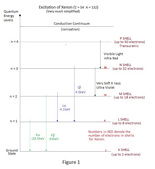
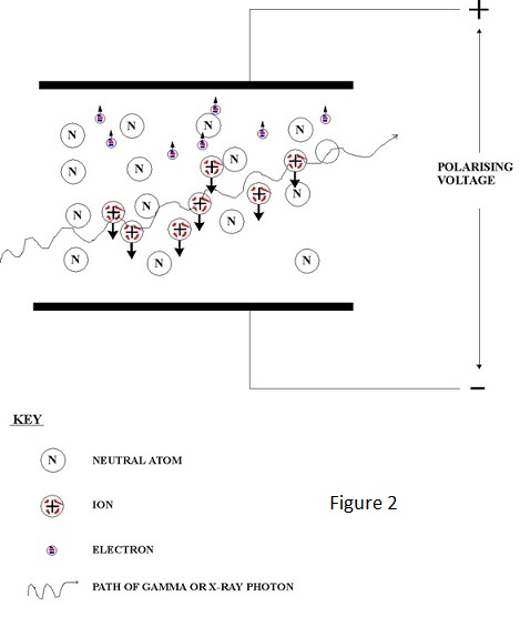
For excitation at the higher enegy levels close to ionisation, fall back is accompanied by the emission of a very soft x ray photon i.e. one of energy slightly less than the actual ionisation energy - typically 15 eV or lower.  This gives rise to an interesting possibility:-

Consider the situation of a chamber filled with a mixture of two gases, one of which has an ionisation energy lower that the energy of the excitation photon emitted by the other.  In these circumstances the excitation photon of the latter is almost certain to ionise the former - the probability of interaction being much greater when the incident and ionisation energy levels are close - and W for some mixed gases is consequently lower than that for either of the individual components.  The effect of an x or gamma ray interaction with an atom of one gas causing the ionisation of another gas is not confined to excitation, it also occurs with ionisation, because the ionised atom also emits a soft x ray as it restores electron orbits following ejection of an electron.

In fact ionisation chambers often contain mixed gases but, as will be seen in due course, W reduction is not the prime purpose.

It should be noted that gases are very good insulators and the ionisation potentials of 15 Volts or so are high compared to 1 to 2 Volts of semiconductors.

The presence of ion pairs in a gas means that it is electrically charged and the magnitude of the charge is a measure of the energy deposited in the gas by the incident radiation i.e. the dose delivered.  To measure a delivered dose it is necessary to measure the total charge produced which is the product of ionisation current and time and consequently measurement of dose rate is achieved directly by the measurement of the ionisation current.

The ionised gas contains essentially static ions and mobile electrons which are only too keen find each other and to recombine.  To constitute a flow of ionisation current it is necessary to separate them by an electric field which is created by the application of voltage to collecting electrodes as shown in Figure 2.

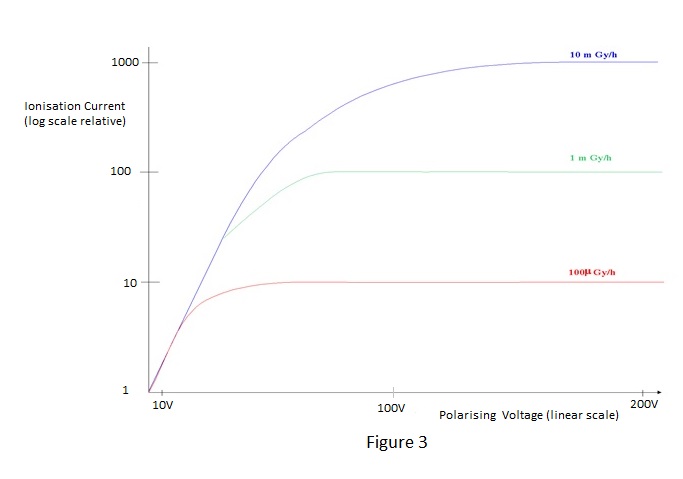
The total current flow is constituted by a flow of electrons to the positive electrode and a flow of positive ions to the negative electrode.  The applied voltage is known as the 'polarising voltage'. Because the ions are very slow moving relative to electrons under the influence of an electric field, recombination will occur unless the field, and therefore the polarising voltage, is sufficiently high to prevent it.  Also, the presence of intense ionisation has the effect of reducing the field and consequently a much higher voltage is required for ion collection at high dose-rates than for low ones.  Complete collection is known as 'saturation' and the aim is usually to achieve 95% saturation for the highest dose-rate to be measured.  Too high a field will give the electrons sufficient kinetic energy to produce ionisation themselves and to produce the effect known as 'gas amplification'.  Gas amplification is employed in proportional and Geiger counters, which are outside the scope of this note, and is unlikely to be a problem for practical ionisation chambers.  An example of typical saturation characteristics for varying dose-rates is shown in Figure 3.

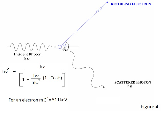
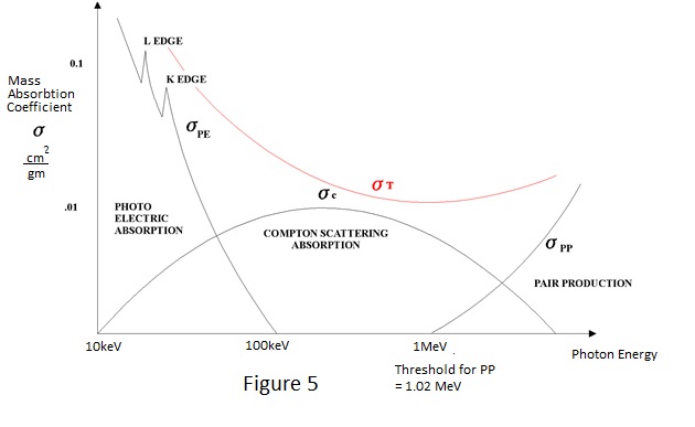
HOW IONISATION OCCURS

By now the author may have given the impression that radiation interacts with matter losing kinetic energy in a series of approximately 15 eV decrements.  This is far from the actual situation and, if it were true, the energy loss would be minimal.

At photon energies normally of interest in radiological protection instrumentation, interactions are initially at much higher energy levels because the radiation interacts with electrons in orbits close to the nucleus or with the nucleus itself and the final level of ionisation is the result of many cascading interactions.  As a result of these higher energy interactions most of the ionisation is due to energetic electrons which lose their kinetic energy more rapidly than photons.

To understand how ionisation chambers  respond to x and g radiation, it is necessary to consider in slightly more detail the three ways in which incident photons interact with matter:

Photoelectric interaction occurs for low photon energies up to about 150keV.  In fact, the ejection of a valence electron at an energy of about 15 eV, as discussed earlier, is a photoelectric interaction.  At energies of interest in radiological protection - 30keV and above - electrons are ejected from the inner orbits around the nucleus in a preferential manner.  This is best illustrated by an example - To eject an electron from the innermost 'K shell' orbits of lead requires energies in excess of 75keV and to eject one from the next 'L shell' requires about 15keV.
An incident 20keV photon can and will interact with an L shell electron but a 100keV photon will interact with a K shell electron much more readily than with an L shell electron.  In fact, the probability of interaction is highest when the energy of the incident photon is just greater than the energy required to liberate an electron from a particular shell, which accounts for peaks in the photoelectric energy response of a given material and its decline with increasing energy.  In a photoelectric interaction an electron is ejected with kinetic energy equal to the difference between that required to remove it and that of the incident photon.  This electron readily causes further ionisation in the material until it is "exhausted" and, as the original target atom rearranges itself to restore equilibrium, it emits a characteristic x ray of slightly lower energy than that required to remove the electron and which itself produces further ionisation.

Compton Scattering is the primary mode of interaction for gamma ray energies in the region 100keV to 1.5MeV effectively taking over where the photoelectric leaves off.  It appears to be the direct result of interaction of an incident photon and any electron and the result is somewhat similar to what might be expected in a collision between electrons.  In a Compton interaction an electron recoils and the incident photon is deflected from its path losing energy in the process.  The energy and direction of the recoiling electron and the energy and direction of the deflected photon can be equated to the energy of the incident photon as depicted in Figure 5.  The Compton scattered photon and electron produce further interactions and ionisation.

Incident photons of energy greater than a threshold of 1.022 MeV can interact directly with the nucleus of a target atom.  In this interaction, known as Pair Production, the nucleus emits an electron and a positron sharing the remaining kinetic energy of the incident photon over and above the threshold level. Of the emitted particles, the electron produces further cascade ionisation in the usual way but the positron is quickly lost in mutual annihilation with another electron.  This annihilation results in two 511keV photons travelling in diametrically opposite directions which themselves can cause further interactions and hence ionisation.  The probability of interaction due to pair production increases with incident photon energy above the threshold energy.

The probability of interaction in a material is known as its cross section or mass absorption coefficient and is quantified in square cm per gram and given the symbol σ.  Tables of σ are available for all materials and most of these are based on the work of a lady by the name of Gladys R White in the 1950s.

A typical variation of the cross section for any material, over the energy range of interest in radiological protection, shown in figure 5.

It should be stressed that, whilst the shape is similar for all materials, magnitudes and the occurrence of photoelectric peaks are of course material dependent.  In a free air ionisation chamber it is the composite cross section of the nitrogen/oxygen mixture which determines its energy response.  In a gas filled practical chamber, the energy response is determined by the composite cross section of the gas or gases and the wall material.  It should be understood that the mass absorption coefficient relates to the nature of the target material, the actual absorption depends on the amount of material present in unit volume i.e. its density 'ρ' and the proportion of energy absorbed per cm - called the linear absorption coefficient 'μ'- is given by σ x ρ.  It is apparent therefore that in a practical ionisation chamber most of the interaction with radiation will take place in the wall, which can cause difficulties as will emerge in due course.  With the right combination of wall and filling gas, it is possible to tailor the cross sections to approximate to the response of an air wall chamber or of human tissue for energy range of interest in radiological protection .

PRACTICAL IONISATION CHAMBERS

There are two distinct advantages in making an ion chamber a sealed vessel:  Firstly, the number of gas molecules within the chamber is fixed so its response becomes independent of changes of atmospheric temperature or pressure and secondly it may be pressurised to increase the proportion of energy deposited in the gas and thereby to raise the sensitivity; the increase being directly proportional to absolute pressure. The main disadvantage is that leak tightness effectively dictates metal containment which can have a complex influence on energy response as will be discussed.

The parallel plate chamber shown conceptually in figure 2 has the main advantage of a uniform electric field for efficient collection of ion pairs but the arrangement is not as physically convenient as a coaxial cylinder, particularly if the chamber is to be pressurised.  A coaxial assembly has, by definition, electrodes of different diameter and its electric field is therefore distorted.  With electrode spacing equal to that of a given parallel plate chamber and the same applied polarising voltage; the field in a coaxial chamber will be weaker near to the outer electrode - where the major part of the collection volume is situated - and more intense near to the inner electrode.  This has a deleterious effect upon the saturation characteristics and consequently coaxial chambers need comparatively higher polarising voltage.

The situation is even worse for spherical chambers.

An interesting phenomenon can be observed in coaxial or spherical chambers, that of self polarisation. 
At low dose rates they behave as is if the outer electrode is at positive potential, presumably due to non-linear charge production and the kinetic energy of the ionised electrons.  If the functionality of an ion chamber instrument is checked at a low dose-rate a faulty polarising supply might go undetected!

The general arrangement of a cylindrical chamber is shown in Figure 6


CHOICE OF FILLING GAS

The choice of filling gas or mixture of gases is determined by both saturation characteristics and the attainment of a desired energy response:-

The original and fundamental unit for exposure dose, the Röentgen, was defined in terms of ionisation produced in air.

Air is almost the worst gas with which to fill a chamber, especially one required to respond to high dose-rates - quite a surprise when one considers the number of air filled chambers around.  The problem is the oxygen content.  Oxygen is what is known as an electronegative gas which means that free electron can readily attach itself to an oxygen atom to form a negative ion.  This negative ion progresses so slowly towards the positive plate that it almost certainly recombines with a positive ion and is lost to the ion current.  For this reason an oxygen filled chamber will have poor polarising characteristics and transient response.  With air the situation is not quite so bad because oxygen content is only of the order of 21% but this is sufficient to cause problems at high dose-rates or when a fast response is required.

As has been mentioned, the wall of an ionisation chamber has a major influence on the energy response of an ionisation chamber and at low photon energies it will absorb so much of the incident radiation as to produce a low energy cut off.  This is not usually a problem because the wall material/thickness can be arranged to 'cut off' at the lower limit of the energy range applicable to radiological protection.  The cut off is of course not abrupt and it defines the shape of the energy response characteristic for low energies.  But what of higher energies?  After all, the object is to obtain a flat or tailored response up to several MeV.  It has also been mentioned that ionisation is the cumulative result of cascading interaction of which the early stage is production of very energetic electrons, particularly energies at which Compton scattering becomes significant.  If the wall is too thin, energetic electrons produced in the outer region will have sufficient energy to carry through the wall into the gas.  These electrons ionise the gas far more readily than photons and there will be proportionally more of them at energies where the photoelectric effect in the wall material is still relatively strong.  The overall effect of these 'secondary electrons' is to produce a marked peaking of the energy response.  For a stainless steel wall this peak occurs at round about 120 keV and for aluminium and plastics at slightly lower energies, dependent on wall thickness and gas filling.  The only way to flatten this peak is to thicken the wall such that the number of secondary electrons absorbed balances the number produced.  The wall is then said to be in electronic equilibrium.  Wall thickening of course greatly impairs the response to lower energy photons and consequently diagnostic or calibration ion chambers, used where the photon energy is known, are often furnished with a number of sleeves to adjust wall thickness. Wall thickening sleeves are obviously inappropriate for the ionisation chamber in a survey monitor but it is possible to compensate for the low energy deficiency of a wall thick enough to give a flat response at higher energies by including a proportion of argon into the counting gas.  Argon has a peak photoelectric cross section around 60keV and a relatively low value for 'W' and, in the correct proportion in an argon/ nitrogen filling,  it can 'peak' the  response sufficiently to correct the fall off due to wall thickness.  Another way of compensating for wall effects, particularly in a chamber having a thin steel wall, is to line it with material of low atomic number 'Z' e.g. aluminium or plastic.  The peak photoelectric cross section energies of materials vary approximately with Z to the fifth power so a thin layer of aluminium can be arranged to absorb excess secondary electrons from a thin steel outer casing and a thin layer of plastic do the same for the aluminium etc.  This way electronic equilibrium can be attained without unacceptable low energy attenuation.  Unfortunately, it does not lend itself to welded construction.  There is no simple way to modify the rising energy response above 1 MeV due to pair production but few long-lived isotopes emit gamma rays above 1.5 MeV, where the effect is still quite small. In any case, pair production occurs in tissue so correction would be inappropriate;  particularly for chambers used in connection with power reactors where gamma energies extend to 10 MeV, due to for example neutron reactions with nitrogen in air.

Figure 7 shows energy response curves for a hypothetical metal walled ionisation chamber showing the effects of the correction methods discussed.

                                                       Units of Measurement 

SI units, for the measurement of radiation dose-rate, have been in use in Europe for a number of years but, because of the continuing use of the original cgs. based units in the USA and the existence of long-lived installed equipment in established facilities, it is still necessary to cross relate the systems of units.  The capacity for confusion increases with the passage of time and this note attempts to simplify matters.

HISTORY

As soon as it was discovered that x-rays were harmful, as well as useful in medicine, it became necessary to measure the amount of radiation given to patients and to express this in terms of a dose.  As the primary effect of x and gamma radiation is to ionise material through which it passes, a practical method for assessing the quantity of radiation is to measure the ionisation produced in gas (air being the most convenient) in an ionisation chamber.  The charge deposited in an ionisation chamber is a direct measure of the ionisation produced by a given amount of radiation and thus can be related to a dose.  A corollary of this is that current flowing in an ionisation chamber is a measure of the rate of radiation and thus relates to dose-rate.

At the time x-rays were discovered, electro-technology was in its infancy and two systems of units had evolved from separate observation of the electrostatic and electromagnetic properties of electricity.  The instrument available for the measurement of charge was the gold leaf electroscope, which is still found in school physics labs.  Operation of the gold leaf electroscope is dependent upon mechanical displacement resulting from the electrostatic force between charged electrodes - the operating principle employed in the present day quartz fibre dosimeter (QFD).

Electrometry being achieved at the time by electrostatic measurement, it was logical therefore to define the unit of radiation in terms of the electrostatic unit (esu) for charge.

UNITS

The agreed unit of radiation exposure became the Röentgen (R) and was defined as the amount of x or gamma radiation which produces 1 esu of charge in 1 cubic centimetre of dry air at normal temperature and pressure (ntp); one esu being 3.3 x 10 exp-10 Coulombs in 'modern' units.

Radiation dose was measured in terms of exposure - Röentgens- for many years but, as radiation produces different amounts of ionisation (and consequently deposits different amounts of energy) in different materials, e.g. tissue, the need was recognised for calibration in terms of the energy deposited in (absorbed by) a given mass of material in order to provide a more meaningful measure of dose.  The derived unit of calibration was called the rad.

One rad is defined as the amount of radiation which deposits 100 ergs of energy per gram of material - the material must be stated e.g. rads (air) or  rads (tissue). Thus a system of practical measurement evolved whereby instruments respond to exposure dose but are calibrated in terms of a calculated absorbed dose for a given material.  It is of course possible to measure absorbed dose directly - e.g. by the heat produced in the material - but at the levels involved in health protection this is hardly practicable.  The erg is a very small unit of energy; one Joule equalling 10 exp 7 ergs.

How does the rad (air) relate to the Röentgen? 
To find this it is necessary to calculate the energy (ergs) deposited in one gram of air subjected to an exposure dose of 1R.

1 esu = 3.3 x 10 exp-10 Coulombs
The charge on an electron is 1.6 x 10 exp-19 Coulombs.
Thus 1 Coulomb = 6.25 x 10 exp 18 ion-electron pairs.
and consequently 1 esu = 3.3 x 10 exp-10 x 6.25 x 10 exp 18 ion pairs
                       = 2.0625 x 10 exp 9 ion pairs.

Now the mean absorbed energy (W) to release one ion pair in air is approximately 32.5 electron volts#, hence 1 esu of charge is the result of the abortion of 2.0625 x 10 exp 9 x 32.5 = 6.764 x 10 exp 10 electron volts in a cubic centimetre of air.

Now 1 Coulomb Volt = 1 Joule and consequently 1 electron volt = 1.6 x 10 exp-19 J 

Thus the energy absorbed per cc for 1R is:
6.764 x 10 exp 10 x 1.6 x 10 exp-19 = 1.082 x 10 exp-8 J or 0.1082 ergs.

Now the density of air at stp. is 1.293 x 10 exp -3 grams/cc. thus the

absorbed energy per gram = (0.1082 x 10 exp 3) / 1.293 = 83.7 ergs 

i.e. just under 84% of a rad(air) as defined.

Therefore 1 rad(air) =  100  = 1.195 Röentgens
                                 83.7
 
A corresponding value for 1R in tissue is approximately 93 ergs per gram and to obtain an energy response corresponding to that of human tissue, ionisation chambers can be made with 'tissue equivalent' walls and filling gases.

So far only gamma and x radiation has been considered but the principles discussed apply equally to ionisation produced by other types of radiation beta, alpha, neutron etc.  In these cases it is necessary to include in the calibration a multiplying factor relating to the biological effectiveness of the radiation( rbe).  The rbe for gammas and x rays is unity but for alphas and neutrons it is much greater.  That is to say that, for a given deposition of energy, the latter have greater physiological effect.

The Röentgen x rbe is the 'radiation equivalent physical' or rep.

The rad x rbe is the 'radiation equivalent man' or rem.
Instruments for a specific purpose, e.g. neutron monitors, were often calibrated in rem.  The rbe for neutrons being between 10 and 20 according to energy.

With the adoption of SI units the unit for absorbed dose became the Gray (Gy) representing an absorbed dose of 1J per kg, an irrationally large unit equivalent to 100rads requiring health related monitoring instruments to be calibrated in mGy.

The Gy x rbe is the Sievert.

There is no SI unit for exposure to directly replace the Röentgen, which the author considers to be a pity, but the Coulomb/kg is an accepted, if less practical unit, for relating radiation fluence to ionisation.

The energy spectrum involved x and gamma dosimetry is wide resulting in penetration into human tissue extending from sub epidermal to complete and relatively recently dose measurement has become depth specific.  Instruments are often calibrated in units of Ambient Dose Equivalence (H*10), relating to the Sievert dose or doserate at a depth of 10mm.  Instruments for β and soft x-radiation dosimetry may be calibrated for lower depths.

Human dose assessment at depth is achieved by measurement within a 'phantom'- a representation of the human torso- with small ionisation chambers or thermo-luminescent dosimeters (tld)s .  Such measurement is predicated upon the Bragg Gray principle which stipulates that the energy deposited in a small 'measuring void' within a material is representative of the energy deposited in the material at the void location.

Field monitoring instruments are required to monitor dose rate, the output from an ionisation volume being current.

From the definition of the Röentgen it is clear that 1R per second will produce a current of
3.3 x 10 exp-10 A in 1 cc at ntp.

Therefore 1R per hour will produce 3.3 x 10 exp-10 / 3.6 x 10 exp 3 = 0.917 x 10 exp-13

Amps per cc or in a practical 1 litre ionisation chamber 0.917 x 10 exp-10 A.

Correspondingly 1Gy(air) per hour will produce:


0.917 x 10 exp -8 / 0.837 = 1.095 x 10 exp -8 Amps

Ionisation chambers are also used to measure the amount of radio-active gas present in the environment in which case the chamber filling gas is sampled from the working environment.  In this case the chamber current represents air concentration i.e. Becquerels per cubic meter. 
A radio-active gas of interest might be tritium which finds extensive use in beta lights .

Tritium emits beta particles of maximum energy 18keV.  However, as will be explained in a further note 'The Atom and Radioactivity' the beta emission spectrum is continuous and that the mean particle kinetic energy is about 6keV.  As the tritium is in air the beta particles ionise the air sample within an ionisation chamber such that on average 32.5 eV# of the particle energy is absorbed by each ionisation.  Thus complete absorption of a tritium beta results in the generation of about:
6000 /32.5 = 185 ion pairs

or 2.96 x 10 exp-17 Coulombs.

Currently the maximum permitted tritium in air concentration is 0.185 MBq per cubic meter which would result in the generation 2.96 x 10 exp-17 x 0.185 x 10 exp 6 = 5.48 x 10 exp-12 Coulombs per second (Amps) in a cubic meter volume. Thus a maximum concentration in air sample in our practical 1 litre chamber would produce a current of 5.48 x 10 exp-15 A.  Because some of the betas are lost to the chamber wall the actual current might be expected to be less than this but, due to their very low energy, tritium betas have very short range in air and wall loss is not significant in tritium monitoring.  


# Subject to variation dependent upon the reference consulted.


Thank you for reading
All content is free to use.