Back to Homepage & Index
This Page - A super-regenerative valve receiver for the 459Mhz Control Band?
Like many others at the time , Co-author of the Norcim site, Terry Tippett, and I were into model aircraft at an early age and, at secondary school in the 1950s, my overarching ambition was to control a model aeroplane by radio.
I read everything on the subject that was printed in the Aeromodeller magazine, having very limited understanding of what I read. However lack of technical knowledge did not diminish my enthusiasm; rather the opposite in fact.
Certainly my pocket money would never stretch to the purchase of the commercial gear then available and, if I was to achieve my goal, I was going to have to make it myself.
(Terry probably got a headstart on me with the help of the local radio repair man)
However freshly demobbed from National service in the RAF, where I learned a little about radio and electronics, I felt ready to pick up the soldering iron and have a go.
I purchased a cheap signal generator and I constructed a simple 2kΩ/V multimeter as a start eventually I adding a simple absorbtion wavemeter for frequency indication.
With this limited test gear I constucted a 27MHz transmitter (see page 8 of the Norcim site) together with soft and hard valve receivers as detailed in page 17 and others of the same.
However, with the lack of suitable crystals for frequency control, operation in the 27MHz band was less than ideal. Only one model could fly in quite a wide area and a proclivity of receivers for latching on to interfering signals caused problems.
It was at this time that I learned that model control was also permitted at 459MHz but it didn't appear to be used.
With the irrepressible enthusiam of youth, I naturally wondered whether I could construct a 459MHz system. After all, I knew about Lecher lines (see page 22 of this site) and the possibility of 'measuring' frequency with a rule was certainly appealing.
The only available uhf. valve (tube) designed for use with dry batteries was the 958A acorn valve and consequently an example was acquired. I was aware that the 958A was specified for operation at frequencies up to 350MHz. but that this was in connection with its use as transmitter valve in 'walkie talkie'
transceivers and I wondered whether low level oscillation could be achieved at higher frequency.
Of course, lacking experience and without test gear, I stood no chance of producing anything workable but my curiosity, with regard to feasibility, endured.
Recently I discovered that the 958A valve is available from Vacuum Tubes Inc. of New Orleans and an example was ordered. It was not expensive but packing, postage and dues treble the cost in the UK.
The valve arrived promptly, new in the box in which it was placed in April 1944.
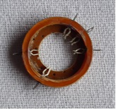
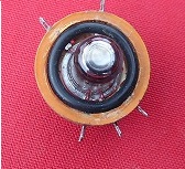
Ad. hoc. holders for acorn valves are virtually unobtainable consequently it was necessary to construct something to facilitate the convenient installation, of what is an awkward component, in a working circuit; the outcome of which exercise is shown in the photographs below.
The construction, which employs sockets removed from a B8G valve holder mounted radially through the wall of a Tufnol ring, was not entirely successful. With the valve body protruding above and below the ring, it was too easy to dislodge the valve when the assembly rested on the bench. This shortcoming was mitigated by fitting the chubby 'O' ring retainer shown in the third photograph.

below, using, where possible, contemporaneous components.
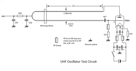
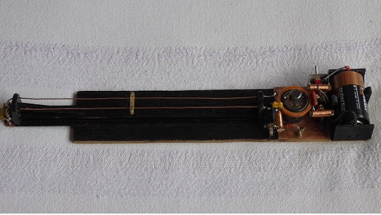
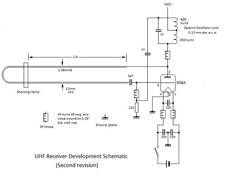
From the photograph it can be seen that the line is extended to enable operation at a low frequency of approximately 300MHz, the highest frequency which I am both able to display and measure with confidence. The brass object, which brdges the line, being a shorting clamp which defines the active length of line for operation at higher frequency.
When switched on with the active length set to maximum, 'squeg' free sinusoidal oscillations were observed on the the oscilloscope and the recorded frequency was 291MHz.
Direct amplitude measurementwas avoided, the scope probe tip and its ground return lead being connected to form a pick-up loop. However the waveform confirmed that the oscillator was behaving as expected.
Based on this apparent success, the clamping bar was repositioned to define an oscillation frequency in the region of 600MHz and, with no means for measurement, oscillation was confirmed with a simple absorption wavemeter as shown below.
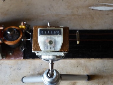
The wavemeter depicted is 'Checker 1' which is untuned except that it has a helical aerial proportioned for 2.4GHz monitoring. Its circuit schematic is shown on Page 22 of the norcim-rc.club site.
Checker 1 is the forerunner of 'Checker 2' a version tuned to 2.4GHz and shown on Page 27 of the site.
Happily Checker 2 is vitually blind to the emanation from the line!
Further Development.
Purchase of a 500MHz oscilloscope being out of the question, an inexpensive frequency counter was purchased.
Non contact, i.e. reliant upon the radiated signal, this was initially found to be quite tricky to use but, once mastered, it confirmed findings to date.
Further development was thus concerned with controlling oscillation by a quench oscillator and, for no specific reason, it was decided that a quench frequency of 50kHz would be tried.
Following 27MHz radio control practice whereby the valve oscillates at both signal and quench frequencies the Clapp oscillator arrangement in the following schematic was as tried unsuccessfully.
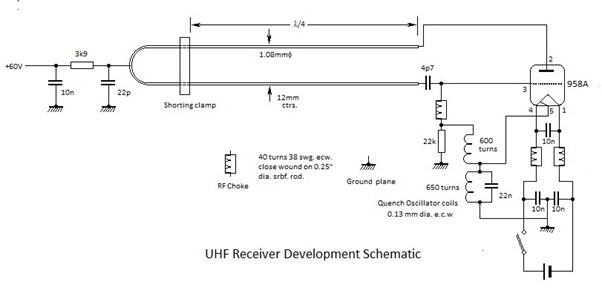
(The quench oscillator coils are apparent in he photograph but they were disconnected for frequency measurement).
The ability for making non-intrusive frequency measurements, permitted further assessment of the Lecher line parameters and, to this object, the shorting bar was repositioned to give an indication of 300MHz.
The line length for this indication was found to be 22.5mm which correponds with the expected propagation velocity of 0.9c. It is reasonable to assume, therefore, that the line impedance is close to the expected 330Ω.
The quench oscillator coils depicted in the schematic and photograph above are typical of those employed in 27MHz receivers in the early 1950s, e.g the Ivy and Hill receivers mentioned in P17 of the Norcim website. These employed two 3mm wide 'pancake' windings beween Paxolin or plywood discs clamped together by a central 6BA brass bolt and nut. Basic paramters are as follows : -
|
* Wire broke but used rather than rewind.
The additive series inductance (primary plus secondary) was found to be 8.25mH; indicating an inter-winding coupling factor of less than 20%. Accordingly the circuit was rearrnged for the tuned anode operation, characteristic of 27MHz practice, as depicted in the following schematic.
As expected this oscillated at 50kHz, controlling the output of the the uhf. oscillator as demonstrated by the oscilloscope trace pictured below: -
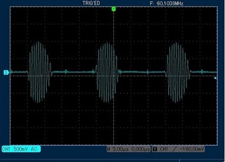
As usual with sensitive super-regenerative circuits a pick-up loop was used to obtain the trace and consequently the voltage scale is arbitary. With the quench oscillator disconnected, the following waveform was obtained with the r.f oscillator running at 260MHz i.e. within the 300MHz bandwidth of the oscilloscope: -
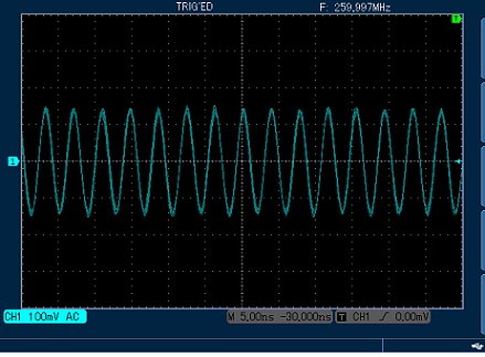
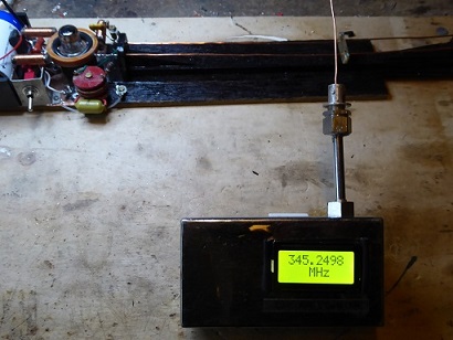
From the trace it can be seen that the oscillator produces a clean sine wave and, with a facility for measuring frequency, the shorting bar was moved down the line to increase the operating frequiency beyond the bandwith limit for the oscilloscope.
However the highest frequncy indication which could be attained was 354MHz. Beyond this oscillation
did not cease as the line was shortened but it apparently went into half frequency mode.
This is not understood, because the author is not comfortable with the concept of sub-harmonics, but it accords with the manufacturer's operational frequency limit of 350MHz for the 958A valve and it demonstrates that oscillation above this frequency is unlikely. Consequently the notion of making 459MHz super-regenerative reciever based upon a 958A valve was a pipe dream.
Thank you for reading.
Anything from this page is free to use.