Back to Homepage & Index
This Page - Super-Regenerative Receivers in early Model Control
In the years immediately following the Second World War radio control of model aircraft became a practical proposition, probably as a result of the development of radio navigation and detection devices during the conflict.
What was required was a small and lightweight dry battery powered detection device, capable of responding to a weak and wandering 27MHz carrier wave signal and, to which, the super-regenerative principle was the answer.
The super-regenerative principle was probably born of the domestic tuned radio frequency (trf.) broadcast receivers of the 1930s, which were in common use prior to the development of the superhetrodyne (superhet) receiver.
As the name suggests, the trf. receivers tuned to the incoming frequency over a waveband.
Because of the wide frequency range covered, the remoteness of some transmitters and amplifier frequency response limitations, the response to stations could be extremely variable; a problem which was largely overcome by the introduction of the superhet receiver and automatic gain control.
However, prior to the advent of the superhet receiver, it was well known that the gain of a given trf. receiver could be enhanced by the application of positive feedback, provided that the feedback was insufficient to cause oscillation.
Positive feedback was effected via a variable potentiometer or capacitor known as the reaction control; which would be used in the following way:- With a weak signal tuned, the reaction control would be gradually advanced. Consequently audio volume would increase in response to this until the RF amplifier burst into oscillation; the idea being to back off the control carefully until oscillation ceased.
However, in the usual way of things, there was considerable hysteresis between position and effect and enhanced performance could only be attained if the advancement could be set just prior to the onset of oscillation; needing skill and patience to attain the best result.
Trf. receivers were thus quite tricky beasts, but it is the author's contention that a good trf. receiver produces a crisper sound than the superhet in the medium and long broadcast wavebands.
Probably the the super-regenerative receiver evolved from need for a very high gain simple single valve receiver for which gain-enhancing positive feedback could be controlled automatically.
Control was effected by arranging for oscillation at the tuned frequency alternatively to build up or be suppressed under the control of a second (quench) oscillator operating at a lower radio frequency.
With this arrangement the tuned amplifier is enabled to start oscillating during one of the half cycles of the quench oscillator waveform and to be suppressed during the following half cycle.
During the enabling half cycle of the quench oscillator, oscillations of the tuned amplifier build up exponentially from circuit noise and the time for them to reach limiting amplitude is inversely proportional
to the Q value of the tuned circuit (number of cycles = Q is a rule of thumb) which is why crystal oscillators take an age to build up.
Therefore, dependent upon the frequency of the quench oscillator, signal frequency oscillation may be permitted to reach full amplitude (logarithmic mode) or be curtailed before doing so (linear mode).
For early radio control applications, the former was perhaps the more appropriate because, as will emerge, sensitivity would be more important than preservation of the shape of a signal modulating waveform such as speech. However, it is important to note that the mean current drawn by the amplifying device (thermionic valve or semiconductor) is dependent upon what is going on in the oscillatory circuit.
If a signal at the tuned frequency is
injected into the oscillatory circuit via an aerial, oscillations build up more rapidly that if they had built up from circuit noise and consequently the mean current drawn by the amplifying device changes as the result of reception of a signal.
In a simple super-regenerative receiver, it is this change which indicates the presence of an incoming signal and, in early valve based receivers, a concomitant reduction of anode current resulted from reception of a signal.
With careful adjustment an electro mechanical relay, energised by anode current through its coil, could be persuaded to de-energise on reception of a signal, thereby controlling a separate actuator circuit via its switch contacts.
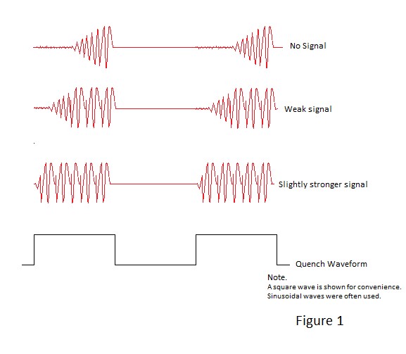
Typical oscillator wave forms are illustrated in Figure 1.
Types.
Three types of super-regenerative receiver were used for radio control of models:-
The hard valve receiver, the soft valve receiver and the transistor based receiver, with circuits appropriate
to single channel, 'Galloping Ghost' and tuned reed operation.
For simplicity circuits depicted in the following illustrations are of the single channel variety.
The more complex of the valve based receivers is the hard valve variety but its operation is easier to understand than its soft vave counterpart.
A typical hard valve receiver schematic is illustrated in Figure 2.
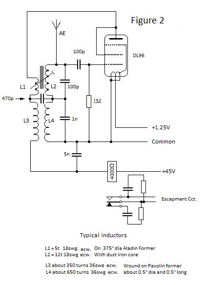
In the figure, the 27Mhz tuned and feedback windings are L2 and L1 respectively and similarly the the tuned and feedback windings for the quench oscillator are L4 and L3.
Sine wave voltages produced by the quench oscillator are dominant in the circuit and are such as to auto bias the valve into class C operation, whereby the action of the CR coupling to the grid and positive grid current is to bias it to a negative potential; causing the valve to conduct only during the positive going half cycles of the waveform. It is only during these half cycles of the quench frequency that the 27MHz oscillator circuit can start and build up amplitude.
Perhaps counter-intuitively the additional 27MHz oscillation causes a reduction of the valve anode current
and, if sufficiently strong, the presence of a signal from the aerial causes the sensitive relay with its operating coil in series with the valve anode to de-energise, breaking the circuit to the sequential escapment operated through its contacts.
For comparison a typical equivalent soft valve receiver is shown in Figure 3.
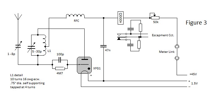
It is apparent from Figure 3 that the soft valve receiver has fewer components than its hard valve counterpart. This is a direct result of the properties of the gas filled triode (Thyratron) valve and it is necessary to have a basic appreciation of these in order to understand how the circuit operates.
Most people are familiar with the mains voltage indicators in electricians' screwdrivers.
These take the form of small cylindrical glass bulbs which contain an inert gas (neon) at low pressure and which have metal electrodes at each end. In use they are connected to a live circuit via a series resistor of around 470kΩ which limits the current to ground, via the indicator and user, to around 300μA and causing the neon gas to glow when the screwdrive blade contacts a live terminal.
The emission of the orange coloured light results from ionisation and excitation of the gas and it is called glow discharge. If measured, the voltage across the indicator bulb would be found to be of the order of 80V and this remains essentially constant irrespective of the current flowing through it; a property
which was utilised in voltage reference tubes in the thermionic valve era.
In fact glow discharge is characterised by a small positive resistance causing the reference voltage to increase slightly with increasing current.
It is apparent from the foregoing that the indicator will not pass significant current and operate in glow discharge unless the applied emf. exceeds 80V. Above this voltage the indicator works equally well for alternating or unidirectional applied emfs. because the indicator bulb electrodes are identical.
However it is unidirectional operation which is the subject of further discussion.
With an applied unidirectional emf; if the current limiting resistance is reduced progressively, the light output increases and the voltage across the bulb increases slightly until a point is reached where it collapses suddenly to around 14 volts, The indicator has now entered the state known as arc discharge.
What has occurred is that the large number of gas ions reaching the negative electrode (cathode) have heated it causing it to emit electrons. In turn, these electrons increase conduction through the gas, causing the inter-electrode voltage drop to a voltage close to the theoretical ionisation voltage for neon
gas, called the burning voltage.
The symmetrical mains indicator bulb does not do this efficiently but special vacuum valves were once
manufactured with cathodes designed to emit copious electrons. These were known as 'cold cathode rectifiers' because the cathode was not heated separately as it is in a thermionic diode rectifier.
An interesting phenomenon relating to the discharge condition is that the orange colour characteristic of glow discharge is observed to change to blue in arc discharge.
(It doesn't actually do so but that is another story).
What is apparent from the foregoing is that it is not possible to achieve arc discharge wirhout first going into glow discharge with a cold cathode. However, if the cathode is heated separately and designed to emit electrons, the arc discharge state may be entered directly with a positive voltage of greater than 14V, termed the striking voltage, applied to the opposite electrode or anode.
It must be stressed however that, even with a source of electrons, arc discharge will only be sustained
if the applied voltage exceeds the ionisation potential and sufficient current is flowing.
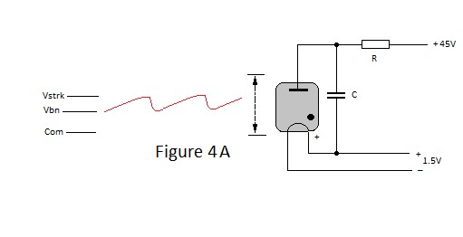
Consider now the circuit depicted in Figure 4A in which a gas-filled thermionic diode is conncected to a 45 volt positive supply via a series resistor and shunted by a capacitor. The value of the resistor is such that, if the diode is shorted circuited, the current which would flow would be less than that necessary to sustain arc discharge. With the diode in situ, current through the resistor will charge the capacitor causing the voltage across it, and the diode, to rise exponentially to striking voltage, at which level arc discharge is initiated. Once struck, the voltage across the diode and the capacitor drops rapidly to burning voltage and remains around this level until the the capacitor can no longer provide sufficient current to sustain the discharge; at which point the discharge is extinguished and the capacitor is free to recharge.
Consequently the circuit is oscillatory with voltage excursions between striking and burning voltage at a rate determined by the CR time constant.
Figure 4B shows the the effect of introducing a negatively biased grid to produce a gas filled triode.
In common with the vacuum triode, the grid electrode controls the proportion of the electrons emitted by the cathode which reach the anode. Negative grid bias therefore 'delays' striking and concomitantly increases the amplitude and reduces the frequency of the oscillation.
However, once struck, negative grid potential has no influence on current whatsoever.
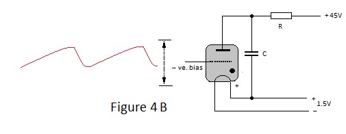
From Figures 4 it can be seen that the thyratron valve can be used in a relaxation oscillator circuit which is capable of fulfilling the function of the quench oscillator for a super-regenerative receiver. However ionisation and de-ionisation take tens of microseconds and that, consequently, there is no possiblity of such an oscillator functioning at 27MHz.
Paradoxically the thyratron valve can sustain oscillation at 27MHz and beyond due to the phenomenon of negative resistance.
It will be remembered that the step from glow discharge to arc discharge involved a dramatic decrease in voltage for an increase of current - effectively a negative resistance step.
This behaviour continues at a very much reduced scale when the arc discharge is 'burning' i.e. the current reduces slightly if the voltage across the discharge rises and vice versa. Arc discharge is therefore charcterised by a small negative resistance. If a tuned circuit is inserted in the anode circuit of a thyratron
valve in arc discharge, it will oscillate if the negative resistance of the arc exceeds the resistive losses of the tuned circuit.
Referring to Figure3 it can be seen that the 27MHz tuned circuit is connected in series with the XFG1 thyratron valve and that feedback to the grid of the valve in conjunction with the resistor and capacitor will bias the grid to a negative potential. The tuned circuit oscillations and quench oscillations are thus interdependent.
Super-regenerative receivers continued to be used for a limited time following the advent of transistors
primarily in moduated quasi proportional systems such as 'Galloping Ghost'. The circuit schematic of the super-regenerative front end circuit used in Terry Tippett's Gallatrol receiver is an example in Figure 5 and which is based on Doug Bolton's 'Flexitone' receiver.
Referring to Figure 5, it is apparent that similar to its soft valve counterpart, there isn't a separate quench oscillator circuit. However a transistor cannot mimic the complex properties of the thyratron valve which permit the latter to function as a relaxation oscillator and, as the author has never built a transistor based super-regenerative receiver, the lack of an autonomous quench oscillator caused a bit of head scratching.
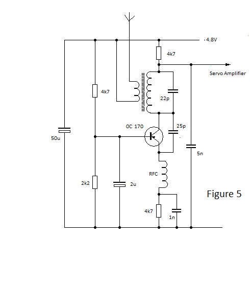
From Figure 5 it can be seen that the transistor is used in the common base configuration to function as an oscillator; employing positive feedback from collector to emitter via a 25pF capacitor.
Calculation of the quiescent voltages in the circuit places the collector at -3.6V and the emitter 1.2V approximately with the transistor passing around 250μA. Thus, with just sufficient feedback to sustain oscillation, the oscillatory voltage at the collector would be expected to approach 4.8V peak to peak.
However feedack via a 25pF capacitor would be excessive at 27MHz; resulting in the emitter-base junction
of the transistor being driven into heavy forward conduction by the positive going excursions of the oscillatory waveform. This diminishes the negative bias applied to the base, causing the transistor to cut off until the base bias network recharges the 2μF capacitor; permitting the transistor to turn on and for oscillation to build up again. Therefore the circuit 'squeggs' i.e. it is self quenching. However a signal intoduced via the aerial with still influence the rate at which oscillations build up and signal modulation can be separated via the low pass RC filter in the collector circuit.
Used in communications the super-regenerative receiver had some useful properties:-
It was very sensitive and would lock on to the strongest signal, suppressing interfering signals.
(Possibly of doubtful advantage for radio control)
It could as both a receiver and transmitter, permitting full duplex telephony short range communication between receivers, a capability which made it useful as a transponder during the second world war.
For example early IFF equipment used super-regeneration to receive a coded signal and to return a coded reply.
With regard to valve receivers in the 1950s, there was little scope for significant variation from the circuits
depicted in Figures 2 and 3 above for both hard valve and soft valve types respectively. Circuit diagrams for commercial receivers produced by a numberof British manufacturers appeared in an article in the Model Aircraft magazine in April 1957 and one manufacturer Electronic Developments Ltd. offered both types
under their 'Boomerang' label.
The published schematic for the soft valve version is shown in Figure 6 below:

and that for the hard valve version is shown in Figure 7 (E&OE)

Dear reader as mentioned on the index page, pages of the norcim site are are now archived as photocopies at norcim.org. Page 19 and others contain details of circa 1950s commercial receivers and the popular IVY and Hill prototypes.
Also considered in Page 19 of the archived site is the possibility of operating a valve super-regenerative reciever from a single 3 cell actuator battery, (thereby dispensing with the need for separate filament and anode supply batteries) by the use of a voltage converter circuit embodying the quench oscillator.
This would have been practicable in the late 1950s and a possible single battery receiver circuit based upon the XFY10 subminiature valve is breadboarded and tested.
Thank you for reading. All information is free to use.