Several years back all of my radio controlled model aircraft operated on the 35MHz band.
Following the introduction of the 2.4GHz. radio control band, the popularity of 35MHz. band diminished rapidly and a gradual process of replacing the 35MHz. receivers in my fleet commenced.
In theory all that was required was direct substitution of the receivers and removal of the 35MHz. trailing aerial. However in some instances the channel controlling the brushless flight motor would not operate. Investigation demonstrated that data from my Futaba 6EX FASST transmitter is sent at twice the rate used hitherto and that some of the older speed controllers (ESC.s) would not function at this rate, although servos operate as normal. To avoid the expense and effort of replacing old ESC.s I decided to fit in-line circuits which would halve the rate control pulses were fed to the failing ESC.s.
An ad.hoc circuit was designed in 2012, when the replacement process started, and described in page 9 part 2 of the Norcim website (http://norcim-rc.club/Radio9part2.htm) which I share with Terry Tippett, the founder of Micron Radio Control.
The Norcim site is the proper place for this topic and my reason for revisiting it is that I am out of practice with regard to creating web pages and need an excuse to ‘keep my hand in’. A further justification is that original layout on stripboard was a bit large for small models and that I now have a digital scope to display waveforms.
The circuit schematic, depicted in Figure 1, utilised the four nand gates of a CD 4011 CMOS integrated circuit. The first two gates, together with the associated resistors, capacitors and a diode, form a one shot mono-stable circuit triggered by the negative going trailing edge of a positive input pulse via the 1nF input capacitor. The period of this non-retriggerable mono-stable circuit exceeds the 8ms interval between the input pulses from the receiver by around 50% and consequently it can only be triggered by alternate pulses.
Input pulses are also fed via a parallel path to one of the inputs of the third dual input nand gate.
This gate acts as a transmission gate/inverter to positive going input pulses unless it is inhibited by its other input being held negative by the output of mono-stable.
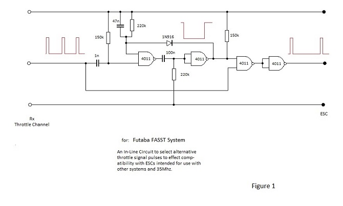
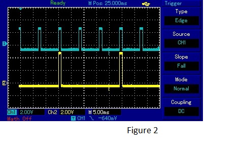
Figure 2 shows the scope traces for the circuit. The blue trace shows the input from a channel of an FrSky TFR8S receiver operating from a four cell NiCad battery. It can be seen that pulses occur at approximately eight second intervals and that their amplitude is around 3.6 V; which is not as high as desirable but it is adequate.
The yellow trace shows the output from the in-line circuit: - Full amplitude pulses normally at half the repetition rate of the blue trace. However in this case the mono-stable period has been extended experimentally to select pulses at one third of the incoming rate which is quite satisfactory for a speed controller.
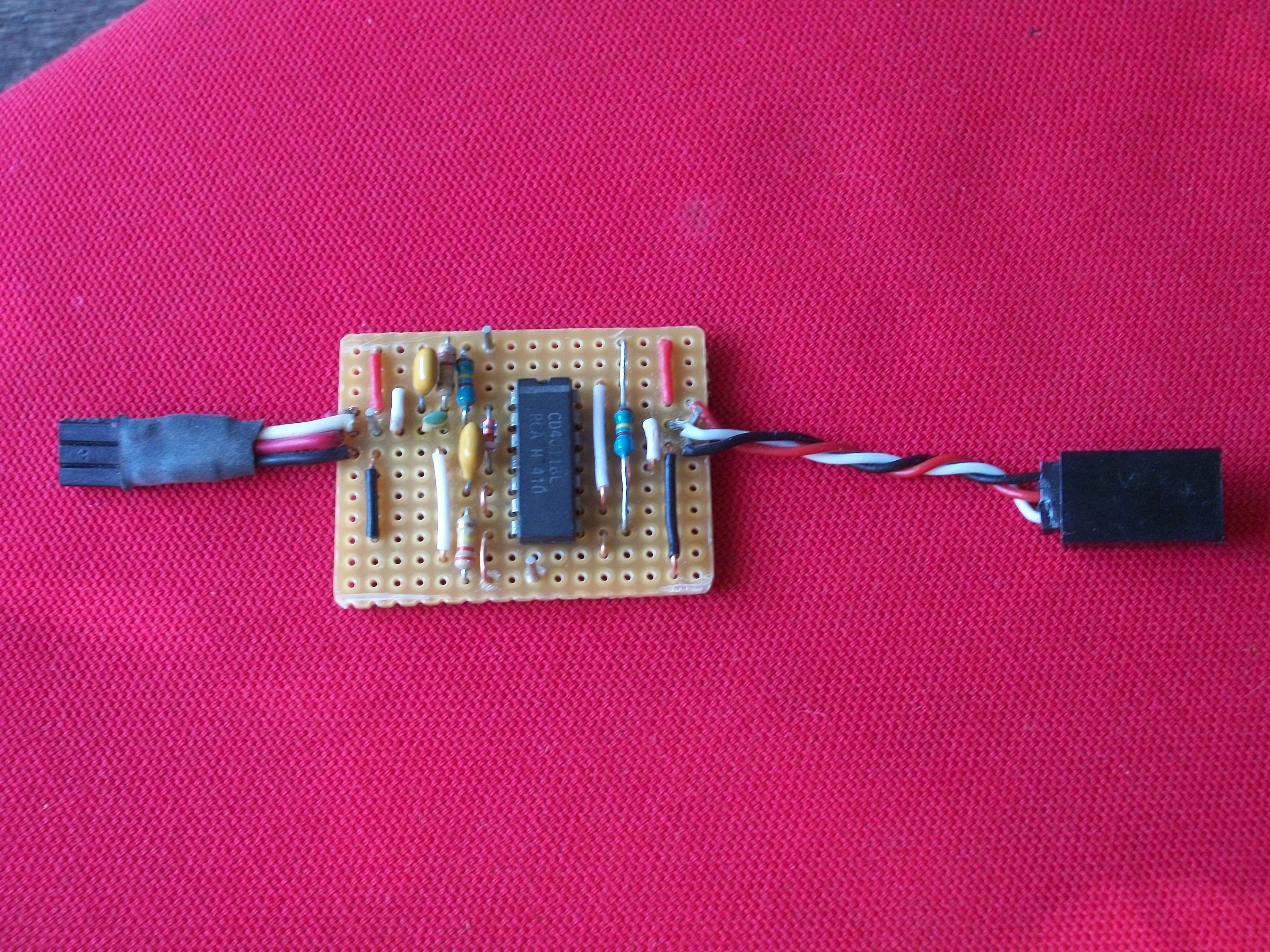
The circuit board assembly is shown in Figure 3 prior to being wrapped in a transparent heat-shrink sleeve.
All information is free for you to use.