This Page - Miscellaneous Technical Information
Signal Diode Charcteristics
Remember the slide Rule?
Oldham Coupling
A simple Audio Wattmeter
Automobile tracking measurement
Moore's Law Impact
Pifco Radiometer
ArcherKit 28-4014A Multimeter.
Audio Amplifier after J Dinsdale.
Construction of a 50A shunt for a DMM.
Signal Diode Charactersitics
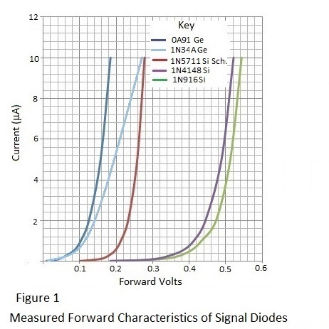
Needing a simple device for indicating the relative signal strength of devices operating in the 2.4 GHz. band some common small signal diodes were considered for possible use as detector diodes. It was expected that a Schottky barrier diode such as 1N5711 would be ideal for this purpose but the reponse for a diode of this type in a simple test circuit was not encouraging although it was significantly better than that for 1N4148 and 1N916 silicon diodes as would be expected. A cheap microwave oven leakage tester was examined to ascertain what type of diode was employed as a detector and it was surprising to find a 'low frequency' Germanium diode type 1N34A was employed. This seemed illogical except it was remembered that point contact Germanium diodes were used as mixers in early radar receivers. A direct current test of this diode showed much better conductivity then the 1N5711 diode at low voltages and it was decided to investigate whether germanium point contact diodes are still obtainable. It was a pleasant surprise to find that the local Maplin store (sadly now defunct) stocked 0A91 diodes, although there can't have been much call for them, and 1N34A gold bonded Germanium diodes or a replacement 1N270 version could be obtained from Farnell.
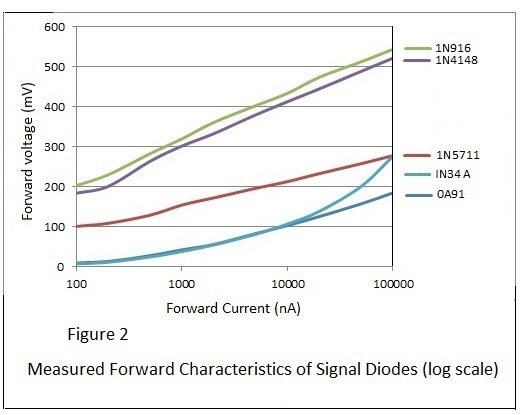
Measured forward conduction characteristics for the signal diodes mentioned are shown in Figures 1&2
The apparently anomalous behaviour of the 1N34A diode tested suggests significant series resistance but this is unlikely because the 1N34A has a relatively high current capability for a signal diode.
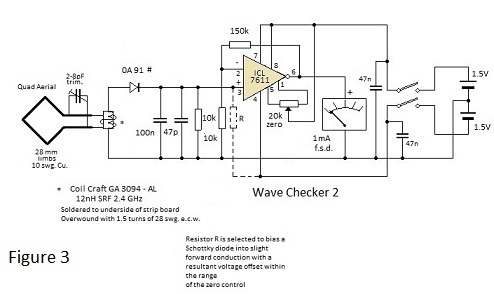
The circuit schematic of the simple signal strength indicator is depicted in Figure 3. Further details of the the device with photographs of it with alternative loop and helical aerials are given on pages 22 and 27 of the Norcim site
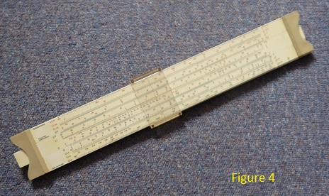
In the latter years of my working career I occasionally used a slide rule to mystify young engineers trained in the age of the electronic calculator. Although these young people understood logs as mathematical functions, most had no concept of tables of logarithms and their use for multiplying and dividing numbers by addition or subtraction of their logarithms or the use of logarithms to raise a number to a different power by multiplying its logarithm by the power index; maybe using logarithms of logarithms if the index was not a simple integer. Consequently a logarithmically scaled rule with a logarithmically scaled slide to effect physical additon or subtraction of parts of the scale in conjunction with a sliding cursor was an object of curiosity. In addition to log scales, slide rules like that illustrated in Figure 4 had as many a six log.log scales (to cover a wide range of power indices both negative and positive). Scales also permitted direct reading of squares and square roots and trig functions using scales on both sides of the rule. The slide rule thus filled the role of todays scientific calculator until the late 1960s.
However it was essential for a slide rule user to know what he was doing because it was necessary for him to determine the position of a decimal point in an answer. Also the significant figures of answers could only be read to a precision of about 1%. and consequently tables of seven figure logarithms were used for more precise calculations.
Professional slide rules made by Thornton (illustrated), BRL, PIC or Nestler were expensive items and many students bought much cheaper rules made by Unique. These had glazed printed paper scales glued to a wooden base and, being single sided, they were limited in capability. However some colleges banned their use in examinations because many of the stock formulae were printed on the reverse side.
Interestingly the popular novelist Neville Shute, who was also an aircraft designer, entitled his auto- biography "Slide Rule".
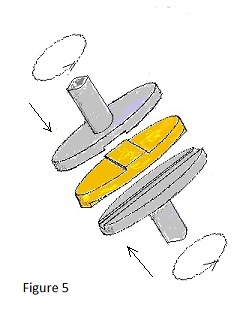
Repairing a car radio many years ago I came across the ingenious little arrangement depicted in Figure 5. It was employed to accommodate significant misalignment between the front panel control and the operating shaft of the tuner behind. I found the way the intermediate disc shuffled about as the control was rotated quite fascinating. Subsequently I discovered that it is called an Oldham Coupling and that it could be found in motor cycle engines; used to accommodate misalignment in the seperable shaft components of the drive to an overhead camshaft. Consequently it must be capable of operating efficiently at several thousand rpm.
Looking for a diode to detect microwaves, as mentioned above, I discovered that Maplin stock Germanium point contact diodes type 0A91. [These are listed as low frequency devices but a quick test demonstrated that they are better for detecting ‘small signals’ than IN5711 Schottky diodes at 2.4GHz].
The availability of these diodes prompted me to revisit an ancient project:
In the early 1970s I was attempting to design a semiconductor based audio amplifier for domestic use. In those days power transistors with a satisfactory frequency limit were expensive and consequently it was advisable to monitor the amplifier power output during testing.
A very simple wattmeter circuit was found in the 1969 Wireless World diary. It was intended for use with a 15 Ohm load and I modified it as I thought necessary for it to operate with an 8 Ohm load. As modified it was wildly inaccurate mid range but at least it served as a safety monitor. It did not get forgotten however and I intended that one day I would see if the accuracy could be improved.
The current availability of Germanium diodes rekindled this interest.
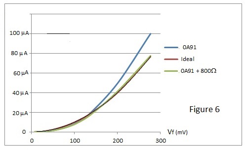
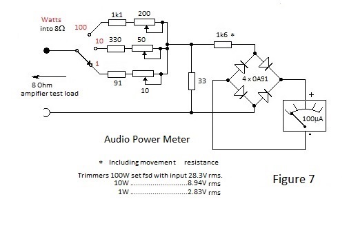
To produce an indication of power it is necessary for the indicating device to respond to the square of the applied voltage and, if ac power is to be displayed on a linear scaled moving coil meter, the rectifier needs to have a square law characteristic.
As shown in Figure 1, forward current through a semiconductor diode varies exponentially with the applied voltage.However, with an appropriate series resistance, the diode characteristic can be made to approximate to a square law as shown in Figure 6; where close to the desired response is attained with a series resistance of 800 Ohms.
 |
Thus, provided that the diode resistor combination can be driven from a low impedance voltage ac.source the rectified current output will be power related.
Figure 7 depicts the schematic for a three range version of the wattmeter. In this circuit the meter is driven by a bridge rectifier so that the series resistance –including the meter movement resistance – is 1.6k Ohms.
Back in the early 1970s I purchased a Morris Minor which had covered little mileage and thus was an almost new car. Surprisingly the nearside front tyre began to wear rapidly and I naturally assumed a tracking error possibly as the result of a kerbing by the previous owner. The tracking was found to be within limits by the local tyre parlour and the tyre was replaced. To my astonishment and dismay the new tyre wore rapidly so the tracking was rechecked and it was again found to be within limits. By this time I was beginning to doubt the accuracy measurements made by the tyre parlour and I schemed up the method for checking the tracking, using a telescopic radio aerial, detailed below.
Ideally the method requires measurements to be made with the unlikely situation of a garage having smooth parallel walls on which horizontal lines about a metre long can be chalked at axle centre height. In practice it is better to screw sturdy battens to the wall at the correct height, using spacers or packing to achieve parallelism; which may verified with a steel tape measure.
Having satisfied this requirement, the method involves measuring the four distances shown in Figure 8. These are between the parallels and the wheel rims (or tyres if so specified) at axle centre height. This is where the telescopic aerial finds its application, serving as an adjustable slip gauge which can be removed for convenient measurement with a steel tape. The gauge is effectively self-adjusting and it is set when its length is at a minimum following sweeps in both horizontal and vertical planes.
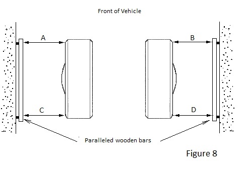
Toe-in is given by (A+B)-(C+D) directly in the units of measurement. If the result is negative the expression gives the magnitude of toe-out.
It is unnecessary for the vehicle to be centrally placed in the garage or for it to be parallel to the walls but it is essential for the steering to be centred and the tyre pressures to be normal.
In order to minimise the effect of the possible distortion of wheel rims, the measurements should be repeated for several positions of the wheels and the average taken. With care result are repeatable within 0.5 mm or less.
Using the method the tracking was found to be spot on; confirming the tyre parlour result. So what on earth could be wrong?
A check from end to end of the steering wheel travel showed that it was not centred in the straight ahead position of the wheels. The car was probably a Friday afternoon product of the British Motor Corporation and the steering links had been adjusted with the steering rack a full turn off centre which resulted in incorrect Ackerman steering angles when turning. Re-setting the tracking with the steering rack centred solved the problem.
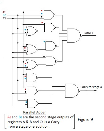
Starting in electronics at the dawn of the digital age when logic gates were constructed from discrete components I never cease to be amazed by the complexity of modern micro circuits having thousands of microscopic components on a tiny chip. I find it even more amazing when I consider the number of gates required simply to sum two binary digits and a possible carry, as depicted in Figure 9. Imagine the number required just to sum the contents of two 64 bit registers.
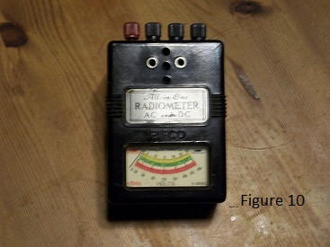
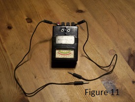
I found the little instrument pictured in the photograph tucked away and forgotten in my shed complete with box, test leads and instructions.
A kind of of forerunner of the multimeter; it is a Pifco Radiometer dating from the 1930s.
Intended to be a diagnostic tool for the wireless set owner, it embodies a moving iron movement which facilitates both ac. and dc. measurements to be made using the appropriate terminals on top of the case.
Measurements in two voltage ranges: 0 to 6 Volts and 0 to 240 Volts are facilitated together with a single current range of 0 to 30 mA. A resistance or continuity facility is also provided, the main purpose for which is to verify the integrity of valve heater filaments. The latter can checked using the test leads but, additionally, the continuity of the heater of a five pin valve can be tested by plugging the valve in to the ad. hoc. socket in the front face of the Radiometer.
A printer’s code on the instruction leaflet suggests that it was printed in 1935 but the Radiometer was advertised in magazines until 1958. Research indicates that, prior to embodying a Bakelite case, the Radiometer was first available as a drum shaped metal cased instrument.
The battery compartment for the continuity test is designed to house an AA size cell but it will accept modern sealed cells only of minimum length tolerance. Presumably the old pitch sealed U7 cells were a ‘few thous’ shorter on average.
With a 33Ω/V burden the Radiometer would be little use for circuit measurements but I guess that this means that a radio HT battery is tested on typical load when its voltage is measured.
Opening the back exposes a very simple repulsion type moving iron movement where two soft iron bars - one fixed, one pivoted - are magnetised within a large coil.
Instruments of this type have a square law characteristic which means that the scale is a bit cramped towards the ends. On the plus side however the indication for ac measurement is true rms.
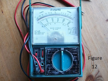
At a vintage car show last summer I was unable to resist the stalls selling bric a brac. On one stall I found a 2” square 500μA meter movement priced at 50 pence. The meter had apparently been part of a piece of test gear manufactured by the British company Pye Ltd.; having the Pye logo featured prominently on the scale plate. I worked for Pye in the early part of my career so I bought the meter for nostalgias sake, although I had absolutely no use for it. I proffered a pound coin but the vendor hadn’t change so I needed to buy something else priced at 50p. The only item of interest was a very grubby blue multi-meter with a long clear scale and, thinking that it might have something useful within I bought it without expectation of it being functional.
However when I examined it later, I found to my astonishment that the movement was sound and that the instrument even contained viable batteries for the resistance ranges; the latter being of French manufacture. A quick check indicated that the voltage and current ranges were pretty accurate although some of the five resistance ranges gave inaccurate indications.
What did impress me was the beautifully damped 20μA movement and that this was the first time I had encountered a 50kΩ/V analogue multi-meter.
Having ‘cut my teeth’ on AVO model 8 multi-meters, I still prefer analogue meters for some measurements and this meter was potentially the most useful analogue meter I had come across. Admittedly it doesn’t have ac. current ranges as does the AVO but this is not a serious disadvantage for measurements relating to electronic circuits .
All in all, I concluded that I had come by a desirable (to me at least) piece of test gear at a bargain price and that it was worthwhile to clean it up and to investigate its origin.
As can be seen from Figure 12, it ‘scrubbed up’ well. The apparent scratching of the control deck is in fact remnants of an original protective film which should have been removed and which now can only be removed with careful and tedious application of a Mk.1 fingernail and spit!
| The logo on the scale plate indicates that the meter was self- assembled from a kit. Investigation confirmed that it was just this and that the kit was a product of the Tandy Corporation with versions appearing under the Micronta and Sears labels, possibly pre-assembled. Out of interest I decided to investigate the anomalous behaviour of the Ohms ranges although they would be unlikely to be used because resistance measurement is better suited to digital multimeters. A manual and circuit schematic would be essential for this and I was pleased to be able to download one from the Internet; scanned and cleaned up by Ken Layton. Thank you Ken! Being for a self-build instrument, the manual is detailed and very comprehensive and I was easily able to ascertain that it had been assembled correctly. However I could make little sense of the component values in the resistance measuring circuits. Remembering difficulty experienced with a college design exercise which required resistor values to be determined for two ranges using a common scale and meter sensitivity but with separate zero adjustment potentiometers. I decided that determining values for five ranges using a common zero adjustment potentiometer and two sources of emf. was going to a daunting exercise and I opted to let sleeping dogs lie, for the time being at least. |
 |
| Yet another Blast from the Past. I discovered the amplifier depicted in Figure 13 during a loft tidying exercise. It was the second of a pair that I built nearly 50 years ago and as such was quite early in the history of semiconductor based audio amplifiers. If my memory serves me right, the amplifiers were broadly based on a design by J. Dinsdale which was published in Wireless World in January 1965. The original design used germanium transistors throughout and I set out to modify it to use more robust Silicon transistors. Apart from biasing considerations Mr Dinsdale’s design for the pre amplifiers was used without modification - after all he had determined all of the gain, filter and equalisation values - but the power output stage of this second amplifier was of my design. |
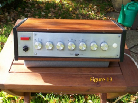 |
As will emerge, the conversion to Silicon transistors was not as straightforward as I imagined it would be. Also the high frequency response of the initial 30 Watt power amplifier using 2N3055 output transistors was disappointing and it was for latter reason that expensive ‘radio frequency’ transistors were used in the output stage of the second amplifier. The r.f. transistors produced a cleaner sound but they restricted the output power to 4 Watts per channel. However 4 Watts was sufficient to rattle the windows with my folded horn speakers.
It was only when the second amplifier had been in use for a while that I noticed that down in the noise radio transmissions could be discerned on both left and right channels. At first I thought that the signals were picked up in the output stages but tests showed that the source of the interference was in the preamps. How, when every effort had been to minimise non linearity, could the amplifier stages demodulate radio transmissions? Eventually it occurred to me that the effective demodulation of what I assumed to be FM. or SSB signals was due to heterodyning. The Silicon transistors in the preamps were apparently producing low amplitude oscillations at radio frequencies as the result of their high transition frequencies compared with those of the original Germanium transistors. A few pF between collector and base of the offending transistors cured the problem.
Why had I not noticed the oscillations? The reason for this was that all I had had at the time was an ancient Cossor 1049 oscilloscope with very limited bandwidth. Nevertheless it was a real double beam scope which had many applications and, with fine calibration of the shift controls, it was a pleasure to use for peak to peak voltage measurements.
Having rediscovered the amplifier a problem now is what to do with it.
Of course the sensible thing would be to retrieve any useful components and to dump it but it is not easy to part with something over which one has spilt blood, sweat and tears and it occurred to me that I might yet have a use for it.
Having to wear digital hearing aids I no longer find pleasure in listening to recorded music due, I assume, to over digitisation – you can only chop up and reassemble a signal a few times before the quality is seriously impaired. This is possibly why my DAB house radio doesn’t sound anywhere as crisp as the FM radio in my car and why the TV and some CDs sound just awful.
However vinyl is back with a vengeance and turntables are readily available so I am tempted to buy a turntable to play the old LPs which I have also found difficult to part with.
Of course 'real audiophiles' swear by valve amplifiers as witnessed by the enduring popularity of books on the subject by my friend and erstwhile colleague Morgan Jones.*
Meanwhile, I am thrilled by the sound from my son’s wind-up gramophone which has nothing whatsoever to do with electronics let alone scratch and rumble filters.
* By Morgan Jones - Valve Amlifiiers 4th. Edition. - Building Valve Amplifiers 2nd. Edition
Available via Amazon.
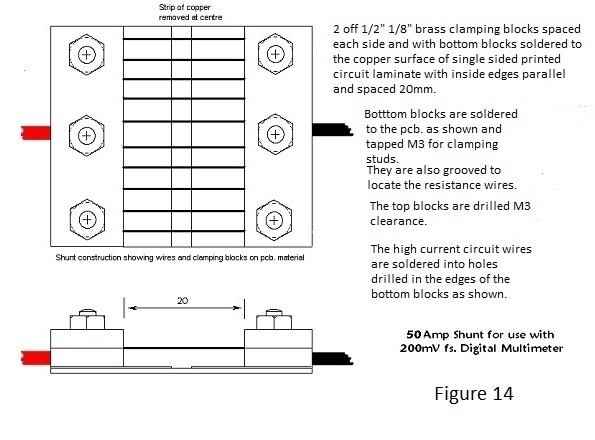
Construction of a 50Amp. shunt for the basic 200mV range of a digital multimeter.
Having need of measurement of the current drawn by motors powering model aircraft, I required a meter capable of measuring 50A or more of direct current. Digital multimeters ususlly have a 10A (sometimes 20A.) full scale current range but this often appears to be wildly inaccurate for basic instruments, which
is not surprising because the shunt often appears to be a loop of copper wire soldered to the circuit
board and it is doubtful whether the 10A fsd. ranges are individually calibrated on all but the most expensive DMMs. Parallel connection of several DMMs to sum readings is impracticable!
However the fundamental 200mV fsd. range of most DMMs. is accurate of necessity and a shunt employing it can yield an accurate indication of current up to 50 A with an acceptable power burden.
However not having a suitable reference current, it would be necessary to design and manufacture a shunt
from first principles of construction robust enough provide a fair meaure of confidence of durability and stability.
50 Amperes at 200mV is 4mΩ and, if this resistance could be attained by parallel connection of 10 Constantan wires, each wire would need to have a resistance of 40mΩ.
The only Constantan wire to hand was 24swg, labelled 1.84Ω per yard. 40mΩ would therefore require a 20mm length and consequently 10 lengths, carefully clamped and soldered between high conductivity blocks spaced 20mm apart, would be a basis for a practicable shunt.
Detailed construction of the shunt is shown in Figure 14.
In the interest of strength, stability and accuracy, the bottom of each pair of blocks is soldered to a glass fibre/copper laminate board spaced 20mm between inside edges. Each of the bottom blocks is also carefully grooved to a depth which ideally is slightly less than the diameter of the wire using a junior hacksaw and the inside faces of all blocks lightly 'tinned' with solder. To ensure straight wires beween the blocks, the laminate is temporarily fastened to a plywood board, thereby facilitating the use of simple drilled wood screw turnbuckles to lightly tension and straighten the wires before clamping the pairs of blocks together. This method is perhaps wasteful of resistance wire but it gives a measure of confidence with respect to achievement of the aim. Once tensioned, top and bottom blocks are clamped together using M3 nuts and washers and block-wire contact is enhanced by using a large soldering iron to heat the top blocks to reflow the solder of the tinned faces as the nuts are tightened evenly and progressively.
Once clamped surplus resistance wire is clipped flush with the outer edges of the blocks and the shunt assembly removed from the plywood board.
"Calibration"
The only indicator conveniently to hand was a 20A fsd. moving iron meter of unknown provenance. Using a 12V battery and fixed resistors it was possible establish and indication appoaching 20A d.c. with the shunt in circuit. The corresponding indication for my most trusted DMM. was pretty much in keeping with expected but the maintenance of a stable current for long enough for certainty proved to be difficult. However being a moving iron instrument, the meter also indicates the rms. value of 50Hz. a.c. current, which raised a possibility. Why not calibrate using a.c. current from a suitable mains tranformer with a single turn secondary? Having a couple of clamp meters to hand which are capable if indicating 50Hz current in excess of 50A, I bargained on wrapping a single turn of thick wire between the coil and the yoke of a mains tranformer and controlling the current in this ad. hoc. secondary circuit by energising the primary via a Variac transformer to faclilitate fine adjustment. Unsurprisingly I couldn't find a transformer with sufficient clearance in the gap between winding and yoke for a thick wire and I hit upon the idea of using the scondary winding of an 'instant' soldering iron, the bit of which constitues part of a single turn and which is plugged into socket receptacles and conveniently retained by clamping screws; the sockets of one to hand being capable of accepting 110/.0076" flexible wire to make a very low impedance current loop.
One of the available clamp meters was an ancient Sangamo Weston unit with a moving coil movement and the other a modern version of Chinese origin with a digital display. In a case of different indications, prejudice inclines me to trust the former. However their indications of 50A circulating in a circuit including the shunt were virtually identical and the the indication for the DMM monitoring the voltage drop across the shunt was encouragingly close to the expected 200mV rms. Even with this relatively stable arrangement, indications had to be recorded quickly because of the restricted duty cycle for the soldering iron transformer at close to full primary voltage but I feel confident that the shunt facilites an indication well within +/- 5% of true with a good DMM. Indications at 20A for all three devices were pretty much identical.