This Page- Vintage Automobile Charging Systems and Electrics
(Dynamo regulators, early alternators and electronic rev. counter schematics also touching on other dashboard instruments).
Regulators
This article sets out to describe, in a non-technical manner, the operation of the Lucas CVC dynamo regulator boxes which were widely used in pre-war and early post war British vehicles. It is intended to assist the owner, who needs to set up the voltage regulator fitted to his vehicle, by explaining the principles governing its operation. It does not however give precise details of the setting-up procedures as these are best obtained from the Lucas data for the model fitted to the vehicle or from the vehicle manufacturer’s workshop manual.
To describe this quite sophisticated piece of equipment in a manner which can be understood by a reader who is not well versed in electro-mechanical technology, it might be beneficial to consider the vehicle dynamo and to introduce the principles governing its operation and control.
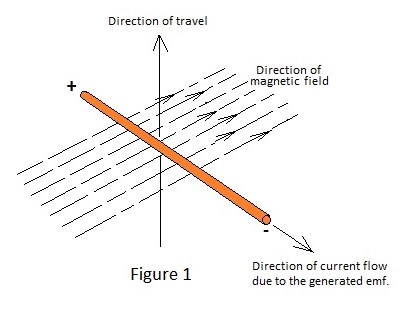
Dynamos and alternators operate by usefully employing the phenomenon that an Electromotive Force (Voltage) is generated in an electrical conductor (wire) as it transverses a magnetic field, as is indicated in Figure 1.
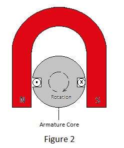
For a practical electric generator a suitable magnetic field exists between the poles (ends) of a horseshoe-shaped magnet. These poles are labelled North (N) and South (S) with respect to the directions to which they would point if the magnet was to be straightened out and used as a compass needle.
The magnetic field is deemed to leave the north pole and to enter the south pole of the magnet in the form of imaginary lines of force; the stronger the magnet, the greater the number of lines.
In a dynamo insulated copper wires are laid in slots which are cut lengthwise around the periphery of an iron cylinder. This cylinder rotates about its axis between the magnet poles which are shaped such that their end surfaces conform to the curved surface of the iron cylinder or core. The rotating assembly of iron and copper conductors is known as the armature and the purpose of the iron core is to concentrate the magnetic field between the poles as it would otherwise disperse and reduce in effect. If examined, the armature core of a dynamo will be found not to be made in one piece but, in fact, will be fabricated from many discs of thin mild steel sheet. This laminated construction minimises inefficiency resulting from electric currents generated within the core itself.
It follows from this that, if a number of conductors are laid in a slot to form a continuous skein or winding with those laid in the slot opposite, the voltage at the open ends of this winding will be increases proportionally.
Many conductors per slot may be required to generate a voltage in excess of 12 volts, particularly at low rotational speeds. In order to be able to use the voltage generated by the rotating winding it must be coupled to stationary terminals by rotary contacts and the simple single- turn winding in Figure 3 is shown connected to two copper rings which are mounted concentrically with the armature shaft. These ‘slip rings’ are electrically insulated from the shaft and each other. Carbon blocks, known as brushes, bear on the slip rings under spring pressure. These are connected by flexible copper braids to static terminals where the voltage generated may be conveniently measured with a volt meter or where connection to an external electric circuit, e.g. a lamp, may be made.
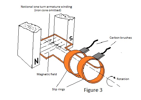
However the simple generator depicted in Figure 3 has a snag; the conductors laid in each of the armature slots are connected to one of the two slip rings and the direction of the voltage generated at a ring, as its conductors pass a pole of the magnet, will reverse as they pass the pole opposite, ie. the voltage appearing at the output terminals will alternate.
Alternating voltage could be used to supply some of a vehicles electrical equipment, e.g. lamps, but it is useless for charging the essential battery and for other facilities.
The simple alternator resulting from the slip-ring-connected armature winding requires a device called a rectifier to convert its alternating output to a unidirectional one suitable for charging the vehicle battery. The alternator fitted to modern vehicles employs a rectifier at the expense of considerable inefficiency, although this is mitigated by other benefits.
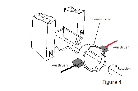
In the dynamo fitted to older vehicles rectification is achieved mechanically by a modification to the slip rings and, in Figure 4, the separate contact rings have been replaced by a single ring which is divided into mutually isolated halves. Also the carbon brushes are positioned on opposite sides of the ring adjacent to the poles of the field magnet. With this arrangement each brush ‘picks up’ the voltage generated by conductors passing its own brush and may be connected to the positive or negative terminal accordingly. The divided slip-ring is known as a commutator.
However the unidirectional voltage generates by this simple machine would still be unsuitable for vehicle electrical equipment, although it could be used to charge the battery. This is because it only generates as conductors pass under its magnetic poles and consequently its output voltage pulsates as the armature rotates.
To obtain a smooth or continuous output, a number of windings are laid in pairs of slots around the cylindrical core and the commutator is further divided into a corresponding number of segments. The windings are also joined at the commutator segments to make the most efficient spacial use of the armature core.
This more developed machine is still unsuitable for use in a motor vehicle because the voltage generated by its windings is proportional to the speed at which they traverse the magnetic field, ie. the rotational speed of the armature as a consequence of engine speed. It is also proportional to the strength of the magnetic field and thus, if this is fixed by the use of a permanent magnet, the output voltage will vary with engine speed; a most unsatisfactory situation.
What is required is a magnet which can be weakened as rotational speed increases so as to maintain the generated voltage at a constant level for all speeds above tick-over. For a 12 volt electrical system about 14.5 volts is ideal; this being sufficient to cause adequate charging current to flow into the battery without being so high as to significantly shorten the life of lamp filaments. The answer to this need is the electromagnet.
When the permanent horseshoe magnet, which has featured in discussion so far, was manufactured, an arrangement basically similar to that shown in Figure 5 was used to magnetise it.
In Figure 5 the horseshoe shaped piece of special alloy steel has been bridged by a piece of pure (or soft) iron to form a closed magnetic circuit. Around this bridge piece are wound a number of turns of insulated copper wire.
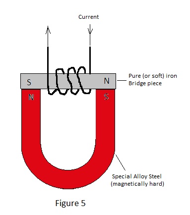
When the current is switched off, the bridge piece will be found to be attached to the horseshoe section by magnetic attraction. However, if the two components are separated, it will be found that, while the horseshoe section will attract other pieces of iron or steel, the bridge piece will not do so. The remenant magnetism of the horseshoe section is a property of the material from which it is made. Suitable alloys of iron, carbon, and other metals exhibit a high degree of remenance after electro-magnetisation; these are known as magnetically hard alloys. The complete loss of magnetism exhibited by the bridge piece only occurs in very pure iron or special alloys and, if the bridge piece had been fabricated from ordinary low carbon steel, it would have retained a small amount of magnetism. Materials that become demagnetised or weakly magnetised after the electro-magnetising force is removed are said to be magnetically soft.
It is this property which facilitates the provision of a variable magnet necessary to control the output of a dynamo or alternator.
If the field assembly of a vehicle dynamo is examined, the arrangement depicted in Figure 6 will be found.
Here the field windings are assembled on shaped pole pieces which are attached to the inner surface of a thick-walled steel tube, which serves as the dynamo body, by large screws.
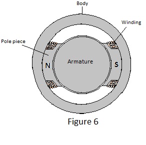
The field components are manufactured from steel which is not completely magnetically soft so that a small magnetic field remains after use. This remnant magnetism is important because the dynamo is self-excited; which means that the current to magnetise the field is derived from the generated output voltage and without a remnant field the machine cannot begin to generate.
Before proceeding further with discussion of how the output of a dynamo is controlled or regulated, it is worthwhile to consider another aspect of simple electro-technology; that of Ohmic resistance.
All conductors resist the flow of electricity and possess the property known as resistance to some degree. For a given material the resistance of a conductor increases in proportion to its length and decreases in proportion to its cross sectional area. Thus a thin long wire has much more resistance than a short fat one for a given amount of material. Also different materials (mainly metals) give widely different values of resistance for a conductor of given size: materials such as copper, silver and aluminium being of low resistance and ones such as iron, nickel, tungsten and carbon being of comparatively high resistance.
The unit by which resistance is measured is called the Ohm after the discoverer of the law which states that current in an electric circuit in Amperes is given by the electro-motive force in Volts, divided by the circuit resistance inn Ohms. For example an emf. of 1 Volt applied to a resistance of 1 Ohm will cause a current of 1 Amp to flow in the circuit, similarly, if a resistance is one of a chain of resistances forming a circuit as shown in Figure 7, a voltage will be ‘dropped’ across it in proportion to the current flowing in the circuit.
This volt drop is given by the current in Amperes (Amps) multiplied by the Ohmic value of the resistance and logically the sum of the individual volt drops across the resistances of the circuit chain must equal the emf. driving the current through the circuit. Volt drop is an important problem in low voltage circuits as may be demonstrated by a simple example.
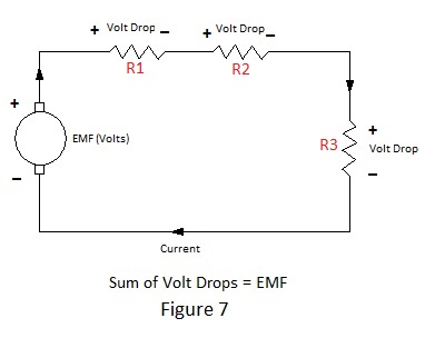
In the circuit of Figure 7 R1 could represent the internal resistance of the dynamo itself (conductors, commutator and brushes), R2 could represent the resistance of the connecting cable (including fuse and switch) to a head lamp load represented by R3.
Now the power dissipated by a resistance is given by the expression:
W = Vsquared/R where W = Power in Watts.
V = Voltage applied to or dropped across the resistor.
R = the ohmic resistance.
We may use the expression to calculate an equivalent value for R3 assuming a typical headlamp load of 96 Watts at 12 Volts.
Ie. 96 = 12squared/R therefore R3 = 144/96 = 1.5 Ohms.
If significant volt drop occurs across resistances R1 and R2, the expression demonstrates how the power taken by R3 will be significantly reduced. A simple numerical example will make this apparent:
Assume that the dynamo emf. is 12 volts and that the internal resistance plus that of the connecting cable (R1 + R2) is 0.5 Ohms The total circuit resistance is therefore (R1 + R2 +R3) = 2 Ohms.
In accordance with Ohm’s law the current taken = V/R = 12/2 = 6 amps.
With this current 6 x 0.5 = 3 volts will be dropped across (R1 =R2) leaving only 9 volts to be usefully applied to the lamps (R3).
Reapplying the expression W = Vsquared/R it can be seen that the power taken by the lamps is 92/1.5 = 54 Watts and consequently the lamps would be rather dim.
This simple example clearly illustrates the need to minimise the internal resistance of the dynamo and the resistance of the wiring by the use of thick conductors and wiring because, when the contact resistances of items like switches, fuses and connectors are included, are included, 0.5 Ohms is not an impossibly high value, particularly for elderly vehicles.
In practice, to satisfy the battery charging requirement mentioned previously, the dynamo emf. is more likely to be about 14.5V which would result in the lamps consuming about 80 Watts with 0.5 Ohms circuit resistance.
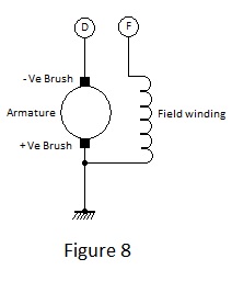
Self excitation of the dynamo field has already been mentioned and, to effect this mode of operation, terminals D and F must be linked such that the current through the field winding results directly from the emf. generated by the armature. Incidentally the field winding is wound from relatively thin wire such that its resistance limits the field current to about 2 Amps at the rated dynamo output voltage.
Direct connection between D and F would, however, result in a very unsatisfactory situation, because, with the field excitation dependent upon output voltage, the latter would tend to increase with the square of the rotational speed. In fact this effect is modified by factors beyond the scope of this article, which limit the effect of field current upon the generated emf. but this will still reach a level in excess of 25 volts at maximum RPM if terminals D and F are directly connected.
To regulate the dynamo output to a constant voltage suitable for charging a battery, it is necessary to vary the field current such that it reduces by the correct amount as speed increases or to provide some slipping clutch and governor to maintain constant rotational speed irrespective of engine speed. Of these options the former is the more practical and less costly although on first consideration this might not be apparent.
To facilitate control of field current, it is necessary to connect a variable resistance between terminals D and F and to automatically adjust its value to achieve a constant output from the dynamo at all speeds in excess of tick over.
The type of variable resistance with which most people are familiar is that commonly used to control the volume of a radio set. Such a device could undoubtedly be used to vary the field current but, for automatic regulation, a motor would be required to position the spindle under what is known as a servo control system. Such a system could be fairly easily designed in the 1980s but in the 1930s such an arrangement would have been difficult construct in a form suitable for use in motor vehicles. The regulator designers therefore developed a method for inserting a fixed resistance between terminals D and F for varying lengths of time. To understand this most elegant solution to the problem of dynamo output control, it is necessary to examine one further item of electro-technology; the electromagnetic relay.
The relay installed in early Lucas CVC regulators has the general form depicted in Figure 9.
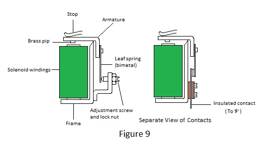
The relay in Figure 9 has an ‘L’ shaped frame formed from steel strip. A steel rod is attached to the base of the ‘L’ to form a ‘U’ shaped assembly. A smaller inverted ‘L’ shaped piece (also called an armature) pivots its internal corner about a knife edge at the top of the vertical limb of the frame. Thus the horizontal limb of the armature closes a magnetic circuit, comprising the frame, rod and armature, when it is rocked towards the end of the rod.
The armature pivots away from the rod through a small angle which is limited by a notionally adjustable stop and it is biased against this stop by a leaf spring which is riveted to its vertical limb to create a narrow gap, of controlled width, in the magnetic circuit. An insulated bobbin, on which are wound a number of turns of enamelled copper wire, is mounted on the rod. This is the energising coil or winding of the relay. When a small electric current passes through the energising coil, the armature is magnetically attracted to the end of the rod against the bias force of the spring and, if the Ampere-turns are sufficient, it will rock to close the gap in the magnetic circuit. In practice a small brass pip on the underside of the armature prevents the gap from becoming fully closed; otherwise it would tend to stick in the energised position when the energising current is switched off. It follows that, if the energised winding has many turns of fine wire, the armature can be made to close by a very small current (remembering that magnetising force is proportional to the product of current and turns) and that the high resistance of this winding may be such that the operating current flows when a minimum voltage is applied to the winding.
Having effected a device which produces limited mechanical movement under the control of an applied voltage or current, it is possible to employ the movement to open or close switch contacts in another circuit. This is why the relay gets its name.
When a relay is used as a voltage regulator, its contacts are arranged to open when it is energised as shown in Figure 9 and these are inserted in the connection between D and F of the dynamo. The energising coil of the relay is connected between D and earth (chassis) and when the dynamo output voltage reaches a level determined by the gap and the strength of the spring bias the contacts open. Having now no field current the dynamo output will collapse which in turn will cause the relay to de-energise and the contacts to reclose. The net result of this interaction between output and excitation is that the relay armature vibrates rapidly and consequently the dynamo output voltage has an average value midway between the relays energising and drop-out voltages irrespective of rotational speed.
By adjustment of the spring bias the average controlled output voltage may be set to a level suitable for charging the battery. To reduce the extremes of the output voltage fluctuation about the average, a fixed resistance is connected across the relay contacts to reduce the fall in output during the periods when the relay is energised, thereby ‘smoothing’ the output.
Having examined the basic principles of generation and regulation in a vehicle electrical system, it is now possible to examine the operation of an actual control box and to discover the meaning of the abbreviation ‘CVC’.
The internal electrical arrangement of a CVC regulator box is shown schematically in Figure 10. Here it will be seen that it in fact contains two relays. One of these is the regulator relay, which has been described, and the other is the cut out relay, the operation of which will evolve in further discussion of operating principles. Each of the relays has a voltage winding comprising many turns of fine wire but these are not visible, being hidden under a layer of insulation material. What will be apparent will be over-windings of thick enamel covered wire. These over-windings, which are shown diagrammatically by bold lines in Figure 10, are current windings. They have a purpose which will become apparent in due course. The current over-windings serve to identify the relays; that for the cut out relay is neat, extending the full length of the bobbin, and that for the regulator tends to be untidy with three terminations and is sometimes wound from copper tape.
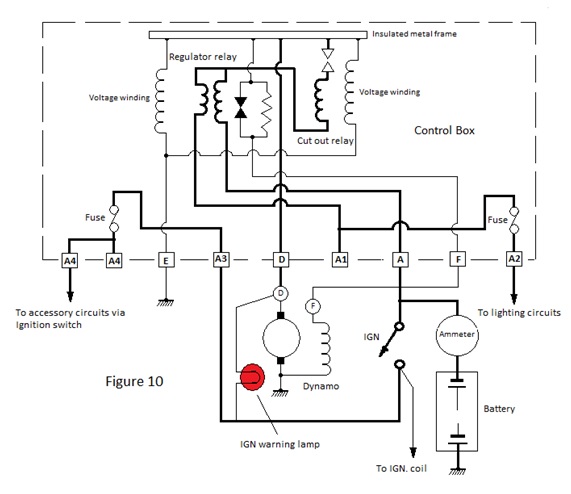
It can be seen from Figure 10 that the D connection from the dynamo output terminal is internally connected to the common frame for both relays which is insulated from vehicle earth (battery positive) by the Bakelite pedestal on which it is mounted together with termination points for the vehicle wiring. Consequently there is a separate earth terminal ‘E’ for connection to the vehicle chassis. The voltage windings of both relays are internally connected between D and E.
Consider first the regulator relay: it can be seen that the current coil is in two sections with a common centre connection. If a current passes from the centre connection through one of the sections it will provide a magnetising force which augments that of the voltage coil but, because the direction of winding is reversed, current through the other section will result in a magnetising force which opposes that for the voltage coil. The aiding section of the current winding is that which is internally connected to the terminal labelled A, from whence it connects externally to the battery via the ammeter. The other end of this section (ie. the common connection) is connected internally to D via the single current winding and contacts of the cut out relay. The purpose of this section of the current winding of the regulator relay is to protect the dynamo from damage caused by excessive charging current which can occur if the battery voltage is low due to prolonged use of the starter motor or if one or more of its cells develop an internal short circuit. The Ampere-turns due to charging current aid those of the voltage winding to lower the dynamo output voltage accordingly.
The other section of the current winding is connected to the terminal labelled A1 and it is via this path that the dynamo supplies current to the vehicles electrical circuits. Because the Ampere-turns of this section partially oppose those of the voltage winding, current through this section causes a small increase of the dynamo output voltage to combat wiring volt drop due to high current loadings. Protection of the dynamo and wiring against short circuits is provided in this case by a fuse which might or might not be incorporated in the regulator box according to model. If the fuse is fitted internally, as in Figure 10, the main electric circuits are connected to terminal A2. Similarly fused circuits feeding accessories connected via the ignition switch are connected to terminal A4.
The current over-windings of the regulator relay thus compensate the dynamo output for the effects of varying demand and this type of regulator is known as Compensated Voltage Control (CVC). Additional compensation is provided for the effect of temperature on the battery voltage and for self heating of the regulator due to the power dissipated in its windings and this is the reason why the setting -up instructions call for adjustments to be made as quickly as possible after starting the engine. Temperature compensation is effected by variation of the spring bias for the armature of the regulator relay; the spring leaf being in fact a bimetal strip.
Readers who have set up a CVC regulator might be puzzled by the fact that the setting-up procedure requires the dynamo output voltage to be set in the region of 16 volts, according to ambient temperature, rather than the approximately 14.5 volts which has featured in the discussion so far. However the instructions also require the external wires to be removed from terminals A and A1 (A2) and to be connected together. This removes the current compensation and without which the dynamo voltage is set to a higher value.
The purpose of the cut out relay is to automatically disconnect the dynamo from the battery when the former is generating a low voltage at tick over. If a cut out is not provided the battery would try to drive the dynamo as a motor under these conditions and it would rapidly become discharged.
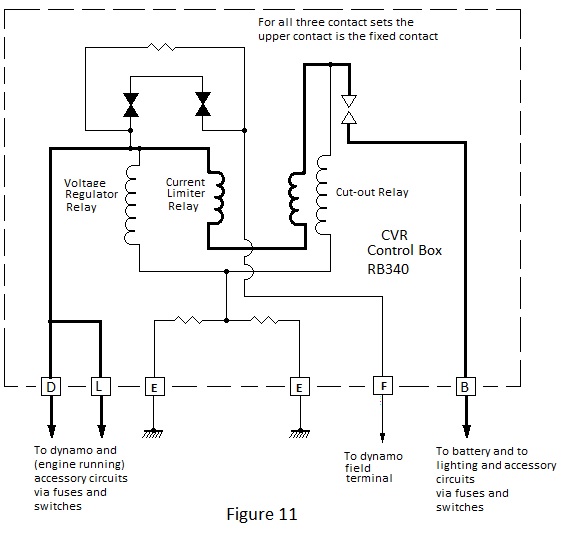
The contacts of the cut out relay are arranged to make when the relay voltage winding is energised by a dynamo output voltage of about 13 volts. Charging current from the dynamo passes through the current over winding of the relay to augment the Ampere turns of the voltage winding but, when the dynamo output voltage drops below that of the battery, the direction of current reverses and a some point the reverse Ampere turns of the current winding completely oppose those of the voltage winding and cause the relay to de-energise, breaking the connection to the dynamo until its output again exceeds the battery voltage. If the dynamo is actually permitted to motor due to a slack drive belt, the magnitude of the reverse current is reduced and the cut out relay fails to de-energise. It is therefore essential to keep the drive belt tight to ensure disconnection. It can be seen from the external connections in Figure10 that the ignition warning lamp is effectively connected across the contacts of the cut out relay and it is thus extinguished when the relay is energised. When the dynamo is stationary a small current flows from the battery to the dynamo via the lamp and it is lit to full brightness. As the rotational speed increases, the difference between the dynamos output voltage and the battery voltage decreases and the brightness of the lamp decreases accordingly, becoming fully extinguished when the contacts close. Towards the end of the dynamo era, three relay regulator boxes were used; the third relay limiting the maximum current output from the dynamo as shown in Figure 11– safer but less elegant than the two relay version when more electrical equipment was beginning to be fitted to vehicles.
Three Brush Dynamos
The foregoing discussion of factors governing the dynamo control system of a motor vehicle having culminated in a description of the CVC control unit, it might be of interest to examine the method of control employed immediately prior to its introduction.
Vintage and early post vintage motor vehicles used dynamos with an additional (third) brush to provide a separate emf. for the control of the excitation current through the field winding.
The additional brush contacted the commutator at a point intermediate between the main brushes to produce a reduced emf for the field winding. Provision was made for the position of this brush to be adjustable over a small arc to vary the maximum output from the dynamo.
Control of the dynamo to suit demand still necessitated the insertion of ohmic resistance in the field circuit but this function was carried out either directly or indirectly by the driver. Early arrangements, which relied directly upon the driver to control the output of the dynamo in accordance with the needs of the battery and working load, used an ad. hoc. control switch labelled ’High’ and ‘Low’ or perhaps ‘Winter’ and ‘Summer’. For daytime operation the Low setting of the switch would be selected to trickle charge the battery and to supply coil ignition if used; the high setting being used for night operation to obtain sufficient brilliance from the headlights. Of course the lights tended to increase in brilliance with engine speed but the third brush system was cleverly arranged to minimise this by application of the property known as armature reaction.
Briefly armature reaction concerns the distortion and concomitant reduction of the magnetising field due to its interaction with the field produced by a current-carrying armature. For a given electrical load, the interfering magnetic field due to current through the armature is dependent upon the generated emf. and hence engine speed and, with careful design of the magnetic circuit, armature reaction can be employed to render the generated emf. essentially constant over a wide speed range. Obviously the stabilising effect of armature reaction can only be effective at full load and the output voltage would be far from constant under low load conditions. However when the dynamo is lightly loaded high charging current will flow into the battery and this itself could be made self- limiting through armature reaction. It is mainly for this reason that the output of vintage dynamos was so low for their physical size; being restricted mainly by the charging current capability of the battery rather than by the demands of load.
With his direct control of the dynamo output, a skilled driver would use the High or Winter setting to quickly recharge the battery after a cold start and remember to switch to the lower setting after a mile or so of daylight running. Failure to switch to the lower setting would shorten the life of either the dynamo or the battery.
To relieve the driver of responsibility of direct control, Lucas embodied three levels of control in the combined ignition/lights switch fitted In vehicles until the early post war period. The complete control arrangement using this switch is shown in Figure 12 which shows the switch in circuit with a control box containing primarily a cut out relay and two field resistors of 1 Ohm and 1.5 Ohms respectively.
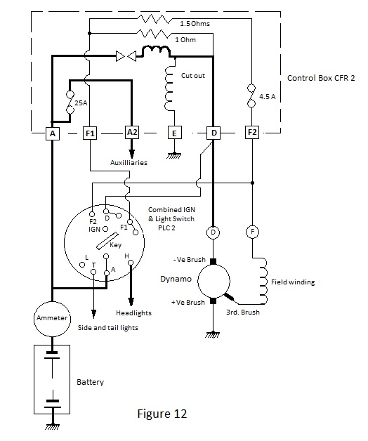
Figure 13 shows the lighting section of the switch in each of the three positions corresponding to: operation without lights, with side/tail lights etc. and with all lights. The switch terminals are labelled either in accordance with their connection to the corresponding terminals of the control box or in accordance with the lighting facility selected. Thus terminals F1, F2, D and A are in the former category and terminals L,T and H are in the latter.
In the first position ’L’ all lights are off and it can be seen that the third brush is connected via the field winding and the F terminal of the dynamo to the F2 terminals of the control box and lighting switch. The F2 terminal of the control box is internally connected via a fuse to the 1.5 Ohm resistor and via the 1 Ohm resistor to the D terminal; from whence it connects externally to the D terminal of the dynamo. Thus the field winding is excited by an emf. which is the difference between the dynamo output voltage and the voltage at the third brush and there is a total of 2.5 Ohms in circuit to limit the field current to a level which produces a dynamo output suitable for trickle charging the battery and powering the coil ignition system. Incidentally exciting the field winding by a voltage which results from the difference in the emfs at the brushes has itself a limited stabilising effect on the dynamo output.
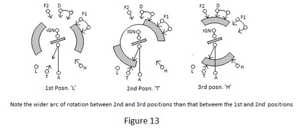
In the second ‘T’ position of the lighting switch the dynamo feeds side tail and panel lamps etc. – moderate load –and in this position the dynamo output terminal is connected to the F1 terminal of the control box, thereby short circuiting the 1 Ohm resistor to leave 1.5 Ohms in circuit with the field winding.
The third ‘H’ position of the lighting switch adds the headlamp load to that of the other lamps. In this position terminals D and F2 are connected to short circuit both resistors such that the field current is limited only by the resistance of the field winding itself and the dynamo gives its maximum output as determined by the position of the third brush.
Early Automobile Alternators
Note:
The following schematics represent the result of reverse engineering of examples prior to disposal and do not necessarily reflect all examples of type.
Automobile alternators are not strictly alternators as such because they do not in fact supply alternating current. However they use alternator principles and the attendant advantages to produce a direct current supply by means of an integral rectifier. Alternators for domestic and industrial supplies generate alternating current in three phases, although for the former only a single phase is normally supplied to an individual household, and likewise automobile alternators normally generate three phases for rectification but single phase ones were once made by a French manufacturer.
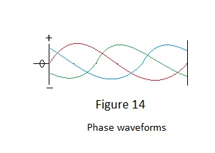
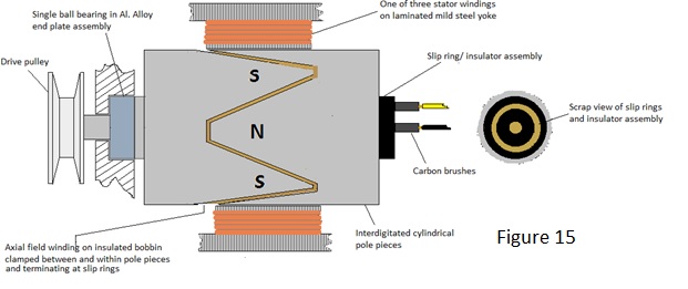
Alternators differ from dynamos mainly in that the output is generated in the stator windings as opposed to the rotor. Voltage is generated in separate three split windings mutually spaced by 120 degrees around the inner periphery of the laminated stator yoke and the exciting field is produced by a simple winding on the rotor which is connected to the control circuit via slip rings. Figure 14 depicts the phase dispersion over the period of one cycle of the three individual sinusoidal phase voltages as red green and blue waveforms and Figure 15 gives a general idea of the mechanical arrangement.
The principle of controlling the alternator output by modulating the field current applies equally to the alternator as to the dynamo; the only difference being that the control for the former is usually by means of an electronic regulator instead of the electro mechanical type formerly used for dynamos.
Silicon junction diodes pressed into an external heat sink were used in the rectifier of some early automobile alternators but the full wave bridge rectifier for the Lucas 17ACR 36 Amp alternator - extensively used in British vehicles of the 1970s - was mounted within the alternator casing and cooled by a fan on the rotor assembly.
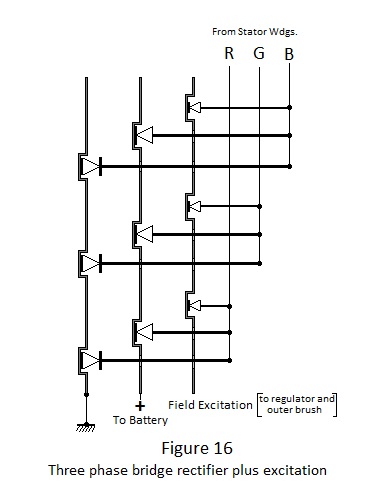
Schottky barrier diodes were used for rectification because their characteristically lower volt drop relative to junction diodes minimises power loss. These were mounted in a finned stack assembly reminiscent of an old fashioned selenium rectifier. The six diodes of the main rectifier were arranged such that their anodes or cathodes were mounted (three of each) directly on one or other of two fins and a third fin embodied three smaller diodes which provided a separate direct current excitation supply for the rotor winding.
An idea of the arrangement is given by Figure 16.
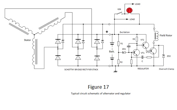
The regulator operates as follows: - With no output from the alternator and the ignition switch off, battery potential of about 12V is applied to potential divider R1 and R2 and the rest of the circuit except VT3. Under this condition, the potential at the junction of R1 and R2 is less than the breakdown voltage of Zener diode ZD1. VT1 therefore does not conduct allowing R3 to provide the base current to turn on VT2, which in turn provides base current drive to VT3. VT3 however does not conduct because there is no voltage supply to its collector via the field winding. When the ignition switch turned on VT3 conducts through the field winding and warning lamp lighting the latter to full brightness providing sufficient field current (2 to 3 Amps) for the alternator to start generating when the engine is started. With the engine running the rectified voltage output from the alternator increases with speed and the ignition lamp dims as this voltage approaches the battery voltage. VT3 can now conduct more heavily because it can draw current from the alternator, providing more field excitation and consequently more output from the alternator. When the alternator rectified output reaches a voltage between 13.6V and 14.4V to potential at the junction of R1 and R2 is sufficient to cause ZD1 to conduct turning on VT1 and turning VTs 2 & 3 off in consequence, removing the field excitation and causing the alternator output to fall. The consequent positive going voltage step at the collector of VT3 is coupled to the base terminal of VT1R1 through capacitor C, enhancing the drive to VT1. Despite the alternator output voltage having fallen ZD1 and VT1 cannot turn off until C has discharged. ZD2 clamps the voltage at the collector of VT3 to a fixed level which otherwise would reach a high potential due to the inductance of the field winding
From this action it can be seen how the rectified alternator output is maintained constant level in the region of 14V, irrespective of engine speed, by pulse modulating the field excitation current much the same way as was done mechanically for the dynamo. This voltage is ideal for taper charging the battery and supplying the working load.
The foregoing is applicable to other Lucas alternators, for example types 14ACR to 20ACR but earlier types 10AC and 11AC did not employ separate diodes for the field excitation, necessitating the use of a relay to disconnect the field winding from the battery when the ignition was switched off, as shown in Figure 18.
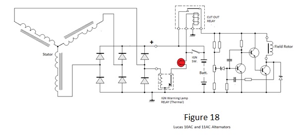
The lack of a separate rectified supply for the excitation also necessitates the use of a separate relay to operate the ignition warning lamp. A thermal device, energised by alternating current from one phase, was used for this purpose. Note also that a trimmer potentiometer is fitted for precise adjustment of the output voltage.
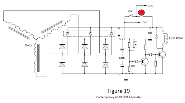
Figure 19 depicts the schematic of a contemporary AC DELCO alternator. As for the Lucas ACR types, this employs a separate rectifier for excitation but the regulator employs fewer components. The lack of positive feedback components in the regulator circuit suggests that the regulator is a linear one.
Early Electronic Rev. Counters.
Warning ‘lamps’ have largely replaced instruments in modern cars but paradoxically most cars now have an engine rev. counter or tachometer when the need for such an instrument is debatable. Hitherto rev counters were fitted only to cars with sporting pretentions, for which there was some merit with regard to obtaining optimum performance. In fact one model of MG dispensed with a speedometer; scaling a rev. counter with equivalent speeds in the upper gears. Rev counters were originally cable driven from the engine cam shaft or in cheaper cars from the rear of the dynamo. Magnetic drag cup instruments were usually fitted to cheaper cars but chronometric instruments were often fitted to more expensive vehicles, particularly ones intended for competition. A reversing gear in the drive train was necessary if the indication was to increase in a clockwise sense and consequently competition cars often had instruments which advanced counter clockwise, presumably to save weight and to minimise frictional losses.
In the early 1960s electronic instruments began to replace the mechanical ones; dispensing with the expensive and noisy cable drive. Externally these instruments were similar to their mechanical counterparts but the drag cup or chronometric movement was replaced by simple electronics and a moving coil meter. One of the most popular cars fitted with early Smith’s electronic rev counters was the MGB. These were discrete component designs which had positive ground circuits until 1967; when car electrics changed to negative ground operation. In the latter stages of production an integrated circuit was introduced. Some years back the writer converted a number of instruments from positive to negative ground and vice versa for MGB buffs and for which purpose it was necessary to do a bit of reverse engineering to produce the circuit schematics shown in Figures 20, 21and 22.
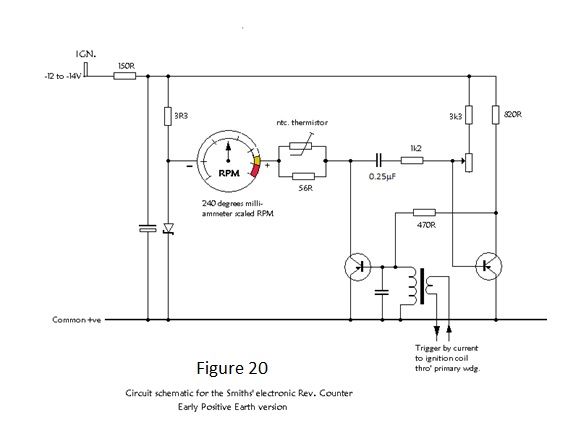
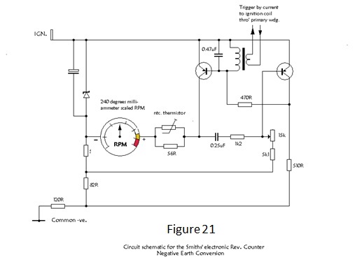
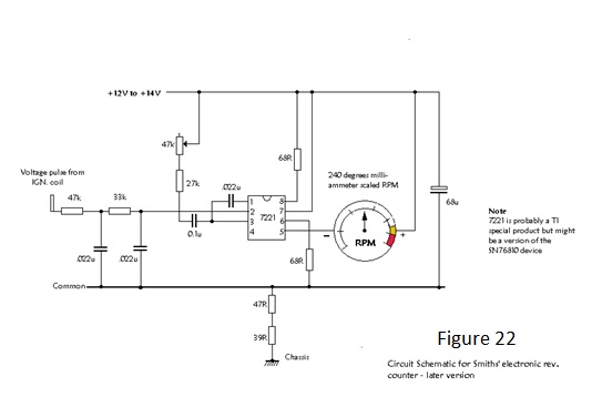
It can be seen that the early examples are current driven whereby a single turn of the wire feeding the ignition coil was passed around a simple transformer yoke. The later design uses the voltage transient on the distributor side of the coil. Either method has its pros and cons.
Ancillary Instruments It is many years since the author pottered with dashboard instruments so the following notes are largely reliant on memory.Temperature Gauges:- Before the late 1960s these were exclusively mechanical Bourdon gauges and thus outside of the scope of these notes. Subsequently electrical temperature gauges employed an ntc. thermistor as the sensing element in conjunction with a hot wire indicator similar to that used to for fuel gauges (see below) at the time. Fuel Gauges:- In the 1930s some luxury vehicles (e.g. Daimler) still had manometer fuel gauges with the tank content indicted by the height of a coloured liquid in a glass capillary tube but electrical fuel gauges were in general use at this time. For these the sensor was a float actuated variable resistor which controlled the current through a moving coil movement according to the level of fuel in the tank; the resistor winding being profiled according to the shape of the tank. However the indication for such a simple arrangement would be subject to significant error due to the normal variation of the supply voltage and to overcome this problem the movement was usually of the dynamometer type with current due to the voltage supply passing through a magnetising coil and current due the sensor passing through the meter coil. With this arrangement increasing sensor current was arranged to drive the indication towards ‘Empty’ with the current due to increasing supply voltage arranged to drive the indication towards ‘Full’. Thus, because the sensor current is itself dependent upon the supply voltage, the indication was independent of supply voltage over its normal range. The main disadvantage of this system was fluctuation of the indication due to cornering forces (the author owned a Riley with a large flat tank and for which a half full indication could register anything between ‘Full ‘and ‘Empty’ on a winding road). This difficulty was overcome in the late 1960s by using a gauge which operated through the expansion of a resistance wire heated by the sensor current and which had, consequently, a ‘long’ thermal time constant to damp out short term fluctuations. However, without stabilisation, the indication for such an instrument would be subject to variation of supply voltage and consequently it was necessary to employ a common ad.hoc. voltage stabiliser for both temperature and fuel gauges. Amazingly voltage ‘stabilisation’ was not achieved by use of a ‘Zener’ diode but by a thermally operated chopper switch, similar to that used for flashing direction indicators at the time. This was mounted on the rear of the dash adjacent to the gauges and it provided a stable average voltage of around 10V for application to gauges and their sensors by variation of the mark to space ratio of commutation between supply and ground potentials ; the thermal time constant of the instruments smoothing the effect of the pulsating supply . |
Ammeters:- |
 |
Solenoids:-
Apart from operating the starter motor switch, solenoids were employed for other applications in older vehicles.
One use was in semaphore direction indicators, where a long narrow vertical solenoid raised an indicator arm via a bell-crank. Another common use was to effect headlight dipping prior to the advent of dual filament bulbs.
Mechanically loaded solenoids need significantly greater current to operate than is required to sustain the operated condition so at the end of travel they are usually arranged to open a normally closed switch contact and thereby to insert a current limiting resistance into the operating circuit.
In the direction indicator application an additional normally open switch was closed to energise a festoon filament lamp within the raised semaphore arm.
Headlights were dipped by tilting the whole parabolic reflector and bulb carrier. This was arranged to tilt downwards and kerb-wards in the un-energised ‘dipped’ state and held by a light spring bias to minimise vibration. Switching to main beam actuated a solenoid which pulled the reflector into the ‘ahead’ position. This solenoid also incorporated a switch to insert current limiting resistance once operated.
Presumably this arrangement was quite expensive because it was usually only incorporated in the nearside lamp; the offside lamp switching off in the dipped position, which can't have been condusive to safety!