The Π Tuned Impedance Matching Circuit.
The Effect of Non-Iterative Successive Time Constants.
Miscellaneous Filter Circuits - Passive and Active.
Twined 'T' Notch Filter.
2nd. Order Sallen and Key Unity Gain Low Pass.
2nd. Order Sallen and Key Unity Gain High Pass.
Avoiding Specific Capacitor Values.
Single Pole Sallen and Key Band Pass Filter.
Baxendall Active Audio Tone Control(s)
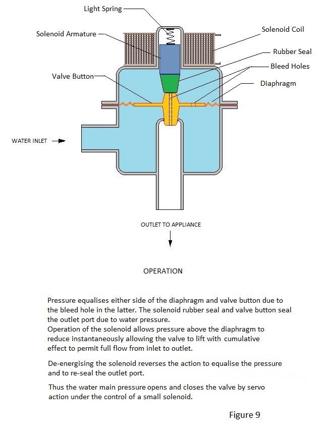
The Mains Water Solenoid Valve
Compton Scattering
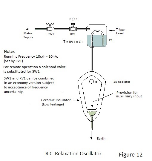
A Ubiquitous RC Relaxation Oscillator.
Light Emitting Diodes - Notes
An Estimation of the Speed of Electron Flow in a Copper Conductor
The Π Tuned Impedance Matching Circuit.
In a transmitter circuit it is essential to match the output impedance of the PA stage to the impedance of the aerial for maximum power transfer. This of course can be achieved by the use of a tuned transformer but matching can also be effected by the use of a Π filter which acts as the load for the PA stage and the source impedance for the aerial. Perhaps astonishingly, this Π filter is symmetrical despite a wide difference in the impedances as depicted in Figure 1.
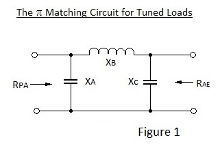
In Figure 1 X denotes the reactances of the inductor and capacitors at the resonant frequency. Perhaps counter intuitively the reactances are all of equal magnitude with :

XC can include the capacitive impedance of the aerial and, because the network is symmetrical, it works in either direction.
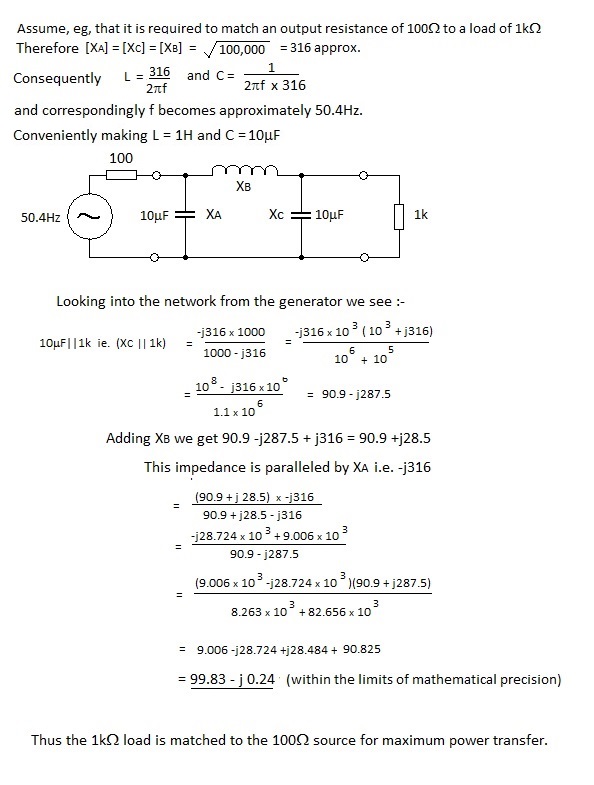
A general proof of the above is tedious but an empirical test might be of interest to readers.
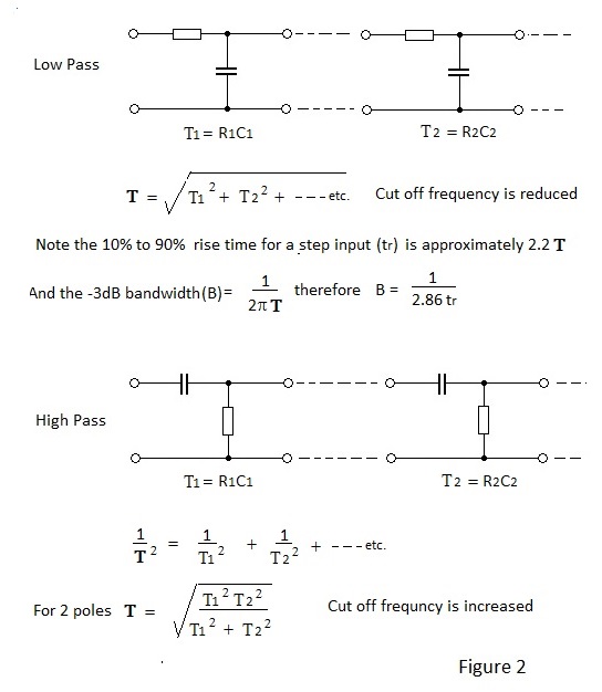
The Effect of Non-iterative Succesive Time Constants.
By non-iterative is meant that the time constants are separated by buffer amplification. For an excellent treatment of the effect of iterative time constants see :-'Laplace Transforms for Electronic Engineers by
J. G. Holbrook - Pergamon Press 1966.
Effects of cascaded low pass and high pass time constants are depicted in Figure 2.
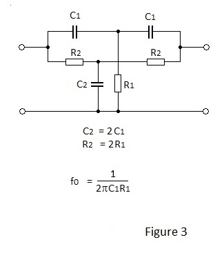
With close tolerance component values, the symmetrical passive filter shown in Figure 3 can produce a dip of 50dB or greater at fo, when driven from a low impedance source and terminated by a high impedance. When capacitors with normal selection tolerance are used the dip will probably be of the order of 30dB. Either side of the dip the phase changes rapidly from +70 to-70 degrees with increasing frequency.
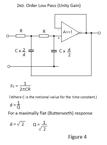
2ND. Order Sallen and Key Active Low Pass Filter.
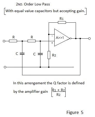
Figure 4 depicts the schematic for a 2ND. Order Low Pass filter with Unity Gain. To effect unity gain different values are necessary for the two capacitors and hence different time constants are employed. If gain is acceptable equal value capacitors may be used as shown in Figure 5.
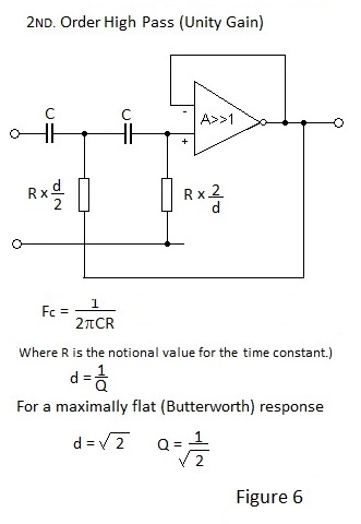
The equivalent unity gain High Pass filter is depicted in Figure 6. Note that the d/2 and 2/d factors for the resistors are applied in locations opposite to those for the capacitors of the Low Pass Filter.
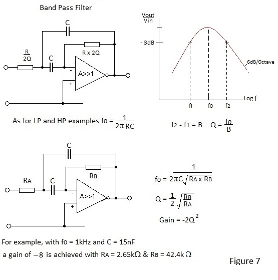
Sallen and Key Active Band Pass Filter
Figure 7 depicts the schematic for an active Band Pass filter with an impression of the response for a specific example.
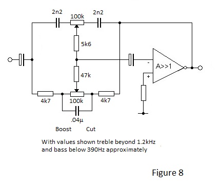
The Baxendall Active Tone Control(s) for Audio Amplifiers
Until P J Baxendall came up with his famous circuit in the 1950s, tone controls for radios and record players were pretty crude. Often a passive 'tone control' did nothing other than act as a bass or treble cut. Baxendall's circuit uniquely permitted an amplifier frequency respose to be progressively lifted or diminished above and below two separate corner frequencies.
An example of a schematic for a typical a Baxendall tone control circuit is shown in Figure 8.
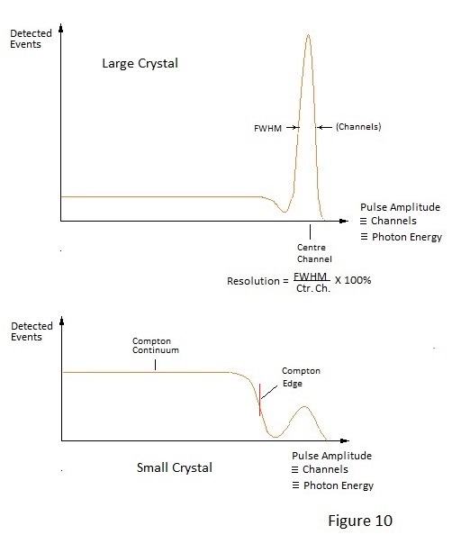
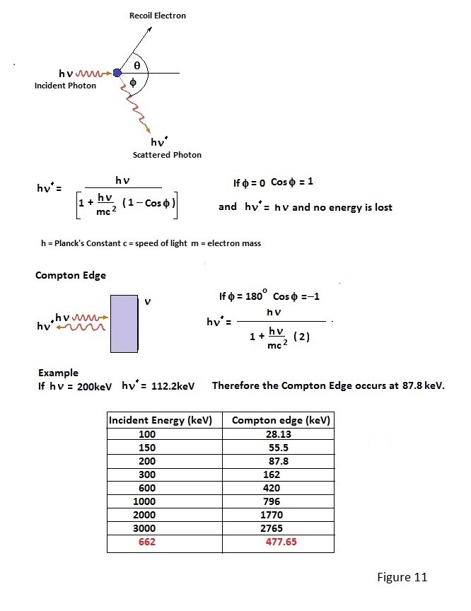
Compton Scattering.
Compton scattering of γ photons as a result of collision with electrons is mentioned in Page 4. It is the primary method of photon energy transfer in the energy range 100keV to 1MeV. If the NaI(Tl) scintillation detector shown in figure 5 of Page 5 is suitably connected to a multi channel analyser (kick sorter), photon energy spectra for various nuclides can be displayed. A typical spectrum for a Caesium 137 source, which emits γ photons of approximately 662keV, is depicted in Figure 10. In fact Figure 10 shows two spectrums; one with a crystal of size sufficient to absorb most of the incident photons and one for which the crystal is too small to totally absorb many of the 662keV photons. Total absorption a γ photon of this energy involves a cascade of energy degading Compton and photoelectric interactions in the scintillator, right down to the production of proportionate visible light photons. Gamma events which are totally absorbed produce a 'photo-peak(s)' characteristic of a given nuclide and which serves to identify it. Events which are not fully absorbed form a continuous spectrum called the Compton Continuum down to zero energy. There is however a dip between the continuum and the photo-peak and the leading edge of this dip is called the Compton Edge. The Compton Edge results from the energy lost by photons which are back- scattered out of a crystal at exactly 180 degrees by single electron interactions; the edge energy being the total energy imparted to such electrons. The energy difference between the Compton Edge and the corresponding photo-peak relates to the energy of the incident γ photon and, with knowledge this relationship, a distinct Compton Edge may be used to determine the energy of incident photons when the photo-peak is poorly resolved.
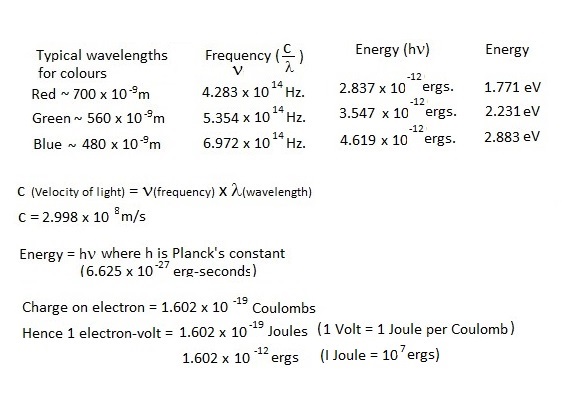
Light is emitted from suitable transparent semiconductor junctions when excited electrons which have been raised to the conduction band fall back to the valance band. The light emitted has essentially a line spectrum of wavelength inversely proportional to the energy gap between bands and consequently materials with wide bandgaps are required to produce shorter wavelengths. This quantum energy gap is conventionally expressed in electron volts and thus, if the light emitted is the result of forward conduction, the forward voltage drop must exceed the bandgap voltage so defined.
The calculated bandgap energies required for various wavelengths are tabulated below. These are the electron -volts required to produce the wavelengths at 0 K and consequently forward voltages for diodes at normal ambient temperature are less than these values.
For example, as mentioned, the bandgap for Silicon is about 1.2V but silicon diodes conduct happily at around half this voltage at room temperature emitting infra-red light.
Consequently light emitting diodes which emit shorter wavelengths are produced from III -IV, and possibly II-VI, compound semiconductors which behave in a similar fashion to single elements from group IV of the simple periodic table and, in the case of early blue green emitters, from the group IV elements silicon and carbon in the form of silicon carbide.
With the compound semiconductors recovery to the ground state is by separate quantum steps according to the materials involved, with the concomitant emission of more than one wavelength. As a result of this it is possible to produce light emitting diodes for which the perceived colour changes with applied voltage e.g. from red through yellow to green.
Blue emitting diodes came on to the scene much later than red, yellow and green diodes but once available it was possible to produce white light from three diode assemblies. Latterly ultra violet emitting diodes have made possible the production of light of any wavelength in conjunction with appropriate scintillation material.
The relationship between forward voltage and colour is shown for several examples in Figure 1. The diodes used to produce these characteristics are basic types ie. not the ultra or hyper bright varieties which might be UV. based
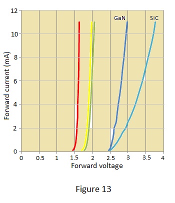
The blue diode characteristics are perhaps worthy of comment with the deep blue (peak wavelength 430 nm) GaN diode requiring a lower and more predictable forward voltage than the blue-green SiC diode. However the latter is an example of a ‘blue’ diode (peak wavelength 470 nm.) produced by Siemens many years before blue diodes became readily available and which was correspondingly very expensive
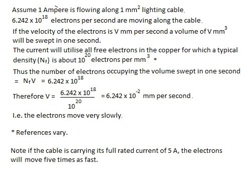
The following is an attempt to estimate the speed of electron travel along a copper wire carrying a steady current of one Ampère:-
All information is free to use.